Centec CTC7132 Switch Core Module
- Introduction
Built upon the Centec CTC7132 SOC solution, this module exposes 32 channels of 10G SerDes interfaces, 1 PCIe x1 interface, 2 SGMII management interfaces, 3 UART interfaces (1 debug serial port + 2 functional serial ports), 4 I2C interfaces (2 for SOC, 2 for PPU), 5 SMI interfaces (1 management port + 4 service ports), 1 100MHz PCIe differential reference clock output interface, a serial LED signal group, etc., via board-to-board high-speed connectors. When used with a carrier board, it can flexibly provide multi-rate, multi-form interfaces to meet diverse application requirements.
-
Hardware Parameters
-
Core board onboard DDR4 capacity: 2GB;
-
Core board onboard eMMC capacity: 8GB;
-
Provides 32 channels of 10G SerDes signal interfaces, supporting SGMII/QSGMII/XAUI/XFI/10G-KR and other modes;
-
Provides 2 SGMII management interfaces;
-
Provides 1 PCIe interface;
-
Provides system operation indicator signals, power indicator signals, over-temperature alarm signals, and configurable service port serial LED stream signals;
-
Provides temperature monitoring function, supports over-temperature power-off, and configurable temperature thresholds;
-
For detailed signal definitions, please refer to Appendix A.
-
Hardware Implementation Scheme
The core board hardware solution mainly consists of the CTC7132 SOC system, power supply, clock, and other system components. It exposes 32 channels of 10G SerDes interfaces, 2 SGMII management interfaces, 1 PCIe 2.0 x1 interface, 3 UART interfaces, 4 I2C interfaces, 5 SMI interfaces, 1 100MHz PCIe differential reference clock output interface, 1 serial LED signal group, and GPIO signals, etc., via board-to-board high-speed connectors. The specific implementation block diagram is shown below.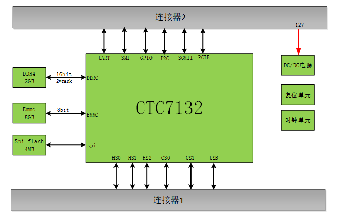
Figure 1 Core Board Schematic Block Diagram
-
Software Features
-
Supports 802.1Q VLAN;
-
Supports VLAN based on IP address and MAC address;
-
Supports STP/RSTP/MSTP protocols;
-
Supports ERPS protocol;
-
Supports static link aggregation, supports LACP aggregation protocol;
-
Supports LLDP link layer discovery protocol;
-
Supports IGMP Snooping function;
-
Supports static routing, supports RIP routing protocol, supports OSPF routing protocol;
-
Supports DHCP Server, DHCP Client;
-
Supports PIM protocol;
-
Supports ACL (filtering, policing, port mirroring), provides filtering based on 5-tuple (source MAC address, destination MAC address, source IP address, destination IP address, port);
-
Supports 802.1X authentication (basic port) function;
-
Supports QoS congestion management, capable of data classification and prioritization;
-
Supports port flow control, supports port isolation;
-
Supports configuration and maintenance via serial port, Telnet, SSH;
-
Supports SNMP V2/V3 protocols;
-
Supports WEB page operation configuration;
-
Structural Dimensions
The core board PCB dimensions are 80mm × 75mm × 2mm (board thickness). The mating height between the core board and the carrier board is 8mm. The TOP side heat dissipation design needs to be considered in conjunction with the actual application scenario. The outline diagram is shown below; refer to the DXF file for details.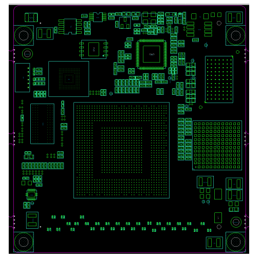
Figure 2 Core Board Outline Diagram (Top View)
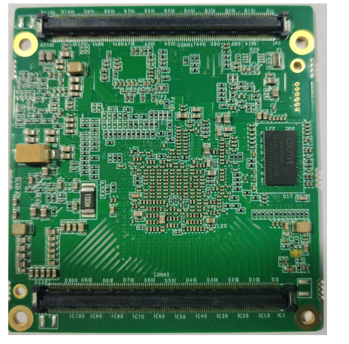
Figure 3 Core Board Outline Diagram (Bottom View)
- Product Physical Photos
Figure 4 Product Physical Photos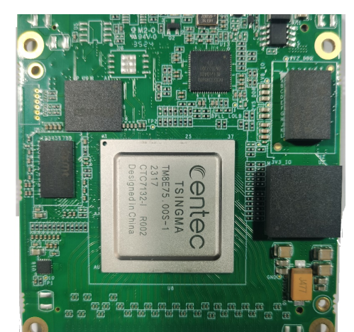
- Connector Selection
No.
Model
Manufacturer
Board-to-board mating height
Remarks
1
RCEF05-D220VG10T
Risunwanxin
8mm
For core board
2
RCEM05-D220VG10T
Risunwanxin
For carrier board
- Localization Parameters
Adopts Centec CTC7132 SOC solution, industrial-grade components, 100% localization rate;
- Power Adaptability
The core board defines DC12V (+/-10%) power input, with a minimum current capability of 3A;
- Environmental Adaptability
Storage Temperature: -55℃~+85℃;
Operating Temperature: -40℃~+70℃.
-
Ordering Model
-
Software Adaptation
The core board supports users adapting software themselves or the designer providing targeted software adaptation according to the user's carrier board design requirements. For specific matters regarding targeted software adaptation, please consult the core board designer's sales personnel. Additionally, targeted software adaptation must adhere to the following constraints in terms of carrier board design:
- PHY devices support CTC21101, CTC21104, CTC21108, YT8618, YT8614, YT8521 series products, etc.;
- When SerDes is routed to the carrier board for port mode configuration, it is necessary to confirm with the core board designer in advance whether there are any constraints;
- When SerDes is routed to the carrier board, if P/N inversion routing needs to be adjusted, it is recommended that RX and TX are inverted simultaneously to maintain synchronization;
- When the SMI bus manages PHY chips of different rates, the specific connection method needs to be confirmed with the core board designer;
- The carrier board design needs to include an EEPROM device (recommended model: FM24C64D-SO-U-G), with its address configured to 0x57, for storing actual adapted service port configuration information;
- The carrier board can optionally include an RTC device based on requirements. The recommended device model is Xingweifan SD2405ALPI-G;
- When placing RTC and EEPROM devices on the carrier board, they need to be connected to the CPU_I2C0 signal definition group. The core board's CPU_I2C0 already occupies addresses 0x48 (temperature sensor) and 0x56 (EEPROM). If more devices need to be placed, care must be taken to avoid address conflicts, and chain-like PCB routing is recommended;