All-Domestic Standard 6U VPX Board Solution Based on Loongson 3A5000 Processor
1**, **Product Features
This product is a highly reliable standard 6U VPX board based on the Loongson 3A5000 processor and 7A2000 chipset, featuring Ethernet, SATA, PCIe, and display interfaces. The product functional block diagram is shown in Figure 1:
Figure 1 System Block Diagram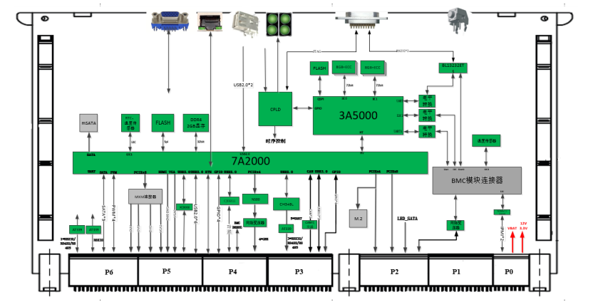
2, Technical Specifications
No.
Item
Specification
Remarks
1
Form Factor
6U VPX
2
Dimensions
233.5mm (L) * 160mm (W) * 25.4mm (H)
3
CPU
Loongson LS3A5000
Industrial-grade, 2.0GHz clock speed
4
Chipset
Loongson LS7A2000
Industrial-grade
5
Memory Capacity
16GB
6
Discrete Graphics Card
1x MXM interface
Jingjia Micro JH920 graphics card
7
Integrated Graphics Card
Loongson LS7A2000
9
BMC
Reserved MCU for BMC functionality
Module form
10
Onboard Storage Interfaces
1x mSATA, 1x M.2 connector
M.2 shares a PCIe x4 lane with the backplane; only one can be used at a time.
11
Operating System
Kylin OS
12
Hardware Watchdog
Supported
13
Front Panel
Gigabit Ethernet Port
1
Universal RJ45 connector, shared with backplane network port 5. Default output from front panel, can be switched to backplane via DIP switch.
14
VGA Interface
1
Universal VGA connector, shared with backplane VGA0. Default output from front panel, can be switched to backplane via DIP switch.
15
USB2.0 Interface
2
Universal USB2.0 connectors
16
CPU Debug Serial Port
1
Led out via HJ30J-18ZKWP7.
Debug serial port shared with backplane, selectable via DIP switch. Default output from front panel.
17
BMC Debug Serial Port
1
18
FPGA JTAG Programming Port
1
19
Indicators
4
System status, HDD status, power status, reserved status
20
Reset Button
1
1 system reset button
21
Rear I/O
Power Supply
DC 12V
Supports single 12V power supply
22
PCIe x8 Expansion Interface Signal
1x PCIe x8
23
PCIe x4 Expansion Interface Signal
1x PCIe x4
24
SATA Signals
3
25
Gigabit Ethernet Interface Signals
5
4 from network card, 1 from chipset, shared with front panel network port, switchable via DIP switch.
26
USB3.0 Interface Signals
2x USB3.0
Compatible with USB2.0
27
USB2.0 Interface Signals
5
28
RS232 Serial Port Signals
1
1x full-function RS232, 460800bps, from chipset;
4x RS232/RS422/RS485, 1Mbps, interface selectable via DIP switch.
29
General Purpose Serial Port Signals
4 (RS232/RS422/RS485 selectable)
30
CPU Debug Serial Port
1
Shared with front panel, switchable via DIP switch.
31
BMC Debug Serial Port
1
Shared with front panel, switchable via DIP switch.
32
BMC IPMI Signals
2
33
BMC Network Signal
1
100Mbps Ethernet port
34
PS/2 Interface Signals
2
1 for mouse, 1 for keyboard
35
Audio Interface
1
Left/right channel output, and microphone input
36
CAN Interface Signals
2
5V level output
37
PWM Interface Signals
2
38
GPIO Signals
8
39
LED Signals
4
SATA indicator, BMC alarm indicator, mainboard power indicator, system running indicator
40
HDD Erase Signal
1
1 erase signal, 1 erase indicator signal
41
Display Interfaces
Integrated graphics 3
Discrete graphics 4
Integrated graphics: DVI0, DVI1, VGA0. VGA0 and DVI0 display the same content in clone mode;
Discrete graphics: VGA1, DVI2, DVI3, DVI4. DVI4 signal series resistor is not soldered by default.
42
Power Consumption
≤80W (with discrete graphics card) ≤50W (with integrated graphics card)
43
Operating Temperature
-40℃ ~ +65℃
44
Storage Temperature
-40℃ ~ +70℃
3, VPX Signal Definition
Definition Principles:
- Complies with the 601 standard;
- Based on the 601 standard, uses vacant pins to add frequently used interface signals;
- For infrequently or rarely used signals, they can be left unconnected when not in use, and connected according to the signal definition when needed.
3.1, P0 Connector
Table A1 Low-Power Logic Computing Blade P0 Connector Pin Interface Signal Definition
Mod P0
RowG
Row F
Row E
Row D
Row C
Row B
Row A