NXP+FPGA-based Permanent Magnet Synchronous Motor Traction Control Unit (Single-Board / Chassis Structure)
Permanent Magnet Synchronous Motor Traction Control Unit (Single-Board / Chassis Structure) 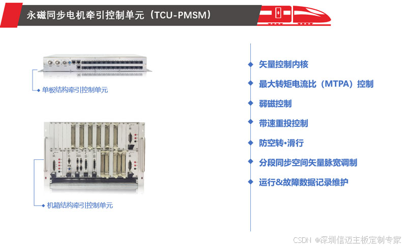
The Permanent Magnet Synchronous Motor Traction Control Unit (TCU-PMSM) is used in traction electric drive systems composed of traction inverters and PMSMs, employing an axle control method. It implements high-performance PMSM complex vector control strategies, featuring rapid response, effective and reliable anti-slip/slide control functions, and smooth, impact-free speed-based re-engagement technology.
Maximum Torque Per Ampere (MTPA) Control and Field Weakening Control The control objectives for PMSMs in rail transit applications are: to control the traction motor to provide sufficiently large torque; and to control the traction motor to expand the speed regulation range while maintaining a constant voltage. Based on the operating characteristics of the PMSM, its operating regions are divided into low-speed and high-speed segments. MTPA control is typically used in the low-speed segment; when the speed exceeds the base frequency, field weakening control is employed to maintain constant power operation.
Speed-based Re-engagement Control In rail transit, after coasting ends or fault recovery, the traction converter needs to be re-engaged. Additionally, excessively high speeds can lead to situations where the no-load back-EMF of the PMSM exceeds the DC bus voltage. A speed-based re-engagement field weakening strategy is adopted to achieve impact-free control.
Anti-Slip/Slide The TCU-PMSM is designed with a high-performance anti-slip/slide control strategy, which effectively and promptly prevents vehicle slip and slide phenomena. Under adverse rail surface conditions, it achieves optimal adhesion utilization, enhancing the vehicle's effective traction force.
Segmented Synchronous Space Vector Pulse Width Modulation High-power traction inverters for rail transit are limited by switching losses and heat dissipation conditions, with switching frequencies generally below 1kHz, and sometimes as low as 500Hz. Low switching frequencies can easily cause problems such as current waveform distortion and torque pulsation. To solve this problem, a multi-mode segmented modulation method is adopted, which includes asynchronous modulation for the low-frequency band, synchronous modulation for the mid-to-high frequency band, and square wave modulation for the high-frequency band.
Operation & Fault Data Recording and Maintenance During train operation, all operational data is stored for analysis of running records. When a fault occurs, operational information around the time of the traction converter fault is separately recorded to facilitate accurate analysis of the fault cause after it occurs. Simultaneously, the corresponding PWM commands and drive feedback waveforms before and after the fault, as well as relevant analog and digital sampled values, are separately recorded. The fault cause can be analyzed by examining the PWM output status.
Technical Parameters: Dimensions (W × H × D): Single-Board Structure TCU-PMSM 480mm × 65mm × 225mm Chassis Structure TCU-PMSM 427mm × 311mm × 290mm Weight: Single-Board Structure 5kg Chassis Structure 18kg (including fan) Input Voltage: 110VDC or 24VDC Operating Temperature Range: –25℃ to +70℃ Communication Interfaces: Single-Board Structure TRDP Ethernet CAN/MVB/Serial Link