NXP+FPGA-Based Rail Transit 3U Chassis Traction Control Unit
NXP+FPGA-Based Rail Transit Asynchronous Motor Traction Control Unit (TCU-IM)
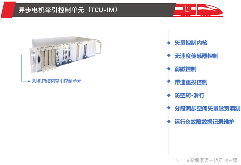
The Asynchronous Motor Traction Control Unit (TCU-IM) is used in traction electric drive systems composed of traction inverters and asynchronous motors, and can be implemented in vehicle-mounted or rack-mounted configurations. It executes high-performance asynchronous motor complex vector control strategies, featuring rapid response, effective and reliable anti-slip/slide control functions, and smooth, shock-free speed-based re-engagement technology.
Sensorless Control By utilizing speed observer algorithms, accurate rotational speed and rotor position are estimated. In practical applications, this eliminates the need for speed sensors, reducing costs and minimizing potential failure points.
Field Weakening Control Considering inverter output voltage and motor current constraints, as well as maximum slip frequency limits, the optimal current control trajectory across the entire frequency range is derived with the objective of maximizing torque output. This controls the traction motor to expand its speed regulation range while maintaining a constant voltage.
Speed-Based Re-engagement Control In rail transit applications, after coasting ends or fault recovery, the traction converter needs to be re-engaged. Additionally, with sensorless control, accurate rotor position identification is required. By employing speed-based re-engagement strategies, shock-free control is achieved.
Anti-Slip/Slide Control The TCU-IM incorporates high-performance anti-slip/slide control strategies, thereby effectively and promptly preventing vehicle wheel slip and slide phenomena. Under adverse rail surface conditions, it achieves optimal adhesion utilization, enhancing the vehicle's effective traction force.
Segmented Synchronous Space Vector Pulse Width Modulation High-power traction inverters used in rail transit are limited by switching losses and heat dissipation conditions. Their switching frequency is generally below 1kHz, and in some cases, only 500Hz. Low switching frequencies can easily lead to issues such as current waveform distortion and torque pulsation. To address this problem, a multi-mode segmented modulation method is employed, utilizing asynchronous modulation for low-frequency bands, synchronous modulation for mid-to-high frequency bands, and square wave modulation for high-frequency bands.
Operation & Fault Data Recording and Maintenance During train operation, all operational data is stored for operational record analysis. When a fault occurs, operational information around the time of the traction converter fault is separately recorded, facilitating accurate analysis of the fault cause after it occurs. Concurrently, the corresponding PWM commands and drive feedback waveforms before and after the fault are separately recorded, along with relevant analog and digital sampled values. The fault cause can be analyzed by examining the PWM output status.
Technical Parameters: Dimensions (W×H×D): 427mm×132mm×230mm Weight: 10kg Input Voltage: 110VDC or 24VDC Operating Temperature Range: –25℃ to +70℃ Communication Interfaces: CAN/MVB/Serial Link