Design and Implementation of Virtualized Devices in Embedded Systems Based on NXP LS1046 + FPGA
3 Design of the Virtualized Device Simulation Platform
The virtualized device designed and implemented in this paper requires building a simulation platform. A robust simulation platform is key to successfully setting up a virtualized device. Building the simulation platform requires specific hardware conditions and, more importantly, a software environment. This section will detail the setup of this virtualization platform.
3.1 Device Simulation Platform Architecture
The hardware environment required for the virtualized device designed in this paper primarily consists of an ARM v8 architecture Linux server acting as the host machine, with no fewer than 16 CPU cores, a hard disk capacity of at least 500GB, and physical memory of at least 32GB. Regarding the software environment, the device simulation platform is mainly divided into three aspects: processor platform simulation, hardware adaptation, and environment deployment. The main control device to be simulated uses an LS1046 processor, and processor simulation employs QEMU virtualization technology. QEMU's development and operation are based on the host Linux system environment, with a recommended Linux kernel version of 3.10 or higher. This development uses open-source QEMU source code, version 3.1.0-rc4. Hardware adaptation utilizes relocatable shared library technology, where shared libraries run within the operating system, and interface libraries encapsulate the Linux operating system's cross-compilation environment. Environment deployment primarily includes the deployment of virtual simulation devices and the establishment of the system-wide network topology. Device deployment is implemented using shell scripts, while a portion of the network topology pertains to processor simulation, achieved via QEMU, and another portion resides in the HOST environment, requiring a virtual bridge environment built with bridge-utils.
3.1.1 Overall Software Solution Model for the Simulation Platform
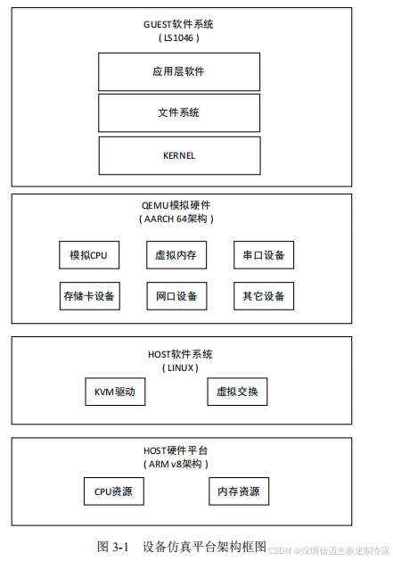
The overall architecture of the device simulation platform is shown in Figure 3-1. It is mainly divided into four layers: HOST hardware platform, HOST software system, QEMU hardware emulation, and GUEST software system.
(1) HOST Hardware Platform Layer:
This layer primarily provides physical resources for CPU and memory emulation to the device simulation platform. The number of CPU cores, CPU clock frequency, and memory size are the three hardware resources that fundamentally determine the overall performance of the device simulation platform.
(2) HOST Software System Layer:
The host operating system in the device simulation platform is primarily divided into two functional aspects: The KVM driver is central to ensuring the performance of the device simulation platform, enabling hardware acceleration for CPU and memory. The virtual switching subsystem forms the basis of the device simulation platform's networking capabilities, supporting network communication between the device simulation platform's internal operating system and the external physical environment, as well as network communication among simulated devices.
(3) QEMU Emulated Hardware Layer:
This layer is responsible for emulating hardware units within the device simulation platform. It is mainly divided into three major parts: CPU, memory, and I/O devices. The specific hardware unit divisions correspond one-to-one with physical devices. This layer primarily serves the kernel portion of the guest software system, allowing the kernel to be unaware whether it is running on actual physical hardware or a virtual simulation device. It is the most critical part of the device simulation platform.
(4) GUEST Software System Layer:
This layer is the software execution layer of the device simulation platform. Vertically divided by function, the lowest layer runs the kernel software of the device simulation platform, responsible for interacting with hardware. Above the kernel, the root file system runs, providing the execution environment for user programs. The uppermost layer is the application layer software that embodies the main functions of the virtual device.
3.1.2 QEMU Emulated Hardware Module Architecture for the Simulation Platform
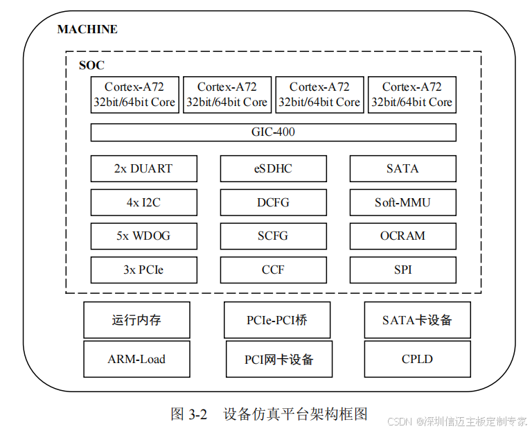
The QEMU emulated hardware module architecture of the device simulation platform is shown in Figure 3-2. It is mainly divided into three layers:
(1) The outermost layer is MACHINE, which corresponds to the physical machine's processor level. It includes the LS1046 processor and related external devices such as memory, network interface devices, PCIe-PCI bridge, external SATA card storage, and CPLD. Additionally, it includes ARM architecture boot units.
(2) The middle layer is SOC, which corresponds to the LS1046 processor. It includes 4 Cortex-A72 ARM cores, an interrupt controller, a serial port controller, a PCIe controller, a SATA controller, and parts of the CCSR system control unit.
(3) The innermost layer consists of specific hardware modules. This part primarily involves simulating address space read/write access, interrupt control, and related functional logic for hardware units.
The QEMU hardware emulation described above only covers the processor level. For board-level peripheral hardware, emulation needs to be performed at the GUEST software system layer. This is achieved by using relocatable shared libraries to intercept hardware initialization functions and hardware functional calls executed by the main control software during its operation on the device, masking subsequent hardware operations and directly returning adaptation and data simulation results.
Specification
Description
Processor
NXP LS1046A at up to 1.4GHz Dual CPU
Storage
Per module 8G DDR4, 8GB eMMC, 16MB QSPI FLASH
Board form factor
Custom board, Dual CPU module
Dimensions
270.00 * 254.99mm
Interfaces
Per module includes 4x 1000MBase-TX RJ45 3x USB2.0 1x RS232 4x RS485
Debug interface
JTAG / COP debug port
3.2 Main Functional Design of the Simulation Platform
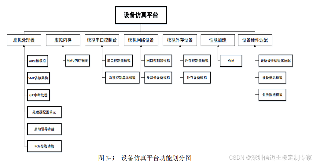
The device simulation platform is divided into the following subsystems according to the functions to be implemented. The functional division of the device simulation platform is shown in Figure 3-3.
(1) Virtual Processor: Emulates ARM architecture CPU cores, emulates SMP multi-core architecture, emulates GIC interrupt mechanism, emulates processor configuration units such as CCF, DCFG, and SCFG, emulates boot functionality, and emulates PCIe bus-related functions.
(2) Virtual Memory: Allocates a specified amount of runtime memory, and emulates the MMU memory management mechanism.
(3) Simulated Serial Console: Emulates a serial port controller, and implements system control commands such as reboot and powerdown.
(4) Simulated Network Devices: Emulates network controllers, and emulates multiple network interface card devices.
(5) Simulated External Storage Devices: Emulates external storage controllers, and emulates external storage card devices.
(6) Performance Acceleration: i.e., the KVM mechanism, which enables hardware acceleration for CPU and memory.
(7) Device Simulation Adaptation: Masks hardware details, adapts to device hardware initialization operations, simulates information such as device type, device presence, and alarms, and simulates partial data for business devices.