【Domestic AI Servers】Advanced Features and Applications of Fully Domestic PCIe 4.0/5.0 Switches, Illustrated with 12Gb SAS Expander Storage Controllers
Many people have probably heard of PCI-E Switch chips, but most likely know very little about their basic functions. As a cutting-edge productivity tool, PCI-E Switches have been widely adopted in traditional storage systems, as well as in a limited number of server brands and models. As a system architect at PMC-Sierra, a company with the world's leading PCI-E Switch products, I'd like to popularize some basic knowledge about PCI-E Switches here.
Background Introduction Everyone is familiar with PCI-E; motherboards have PCI-E slots, and the "golden fingers" inside are a bunch of signal lines directly connected to the CPU's internal PCI-E controller. However, current Intel platform CPUs support a maximum of 40 lanes per CPU. Generally, a 10 Gigabit Ethernet card uses 8 lanes, while high-end graphics cards require x16 lanes due to the massive throughput needed for 3D computations (my PC uses an older motherboard with a GTX980 graphics card, which can only run in x8 mode, but 3D performance is largely unchanged, proving x8 is generally sufficient). General storage cards also use x8, but backend 12Gb/s SAS storage cards (HBA cards, RAID cards) have generally transitioned to x16.
However, for some high-end products, especially traditional storage systems, 40 lanes per CPU often prove insufficient. A specific requirement for traditional storage systems is a large number of backend and frontend HBAs, which means the number of lanes provided by the CPU itself cannot meet the demand. Additionally, traditional storage controllers need to perform various data exchanges and synchronizations, typically also using PCI-E, which further increases the consumption of lanes.
For typical high-end servers, dual-socket or quad-socket configurations are common. A dual-socket setup provides x80 lanes, theoretically allowing connection of 10 x8 PCI-E devices. After accounting for lanes used by management and internal embedded PCI-E devices, connecting 8 devices is straightforward and can cover almost all application scenarios.
However, with users' increasing demands for convergence, unification, efficiency, space, and energy consumption, many high-density modular server platforms, or open blades, have emerged in recent years. These server platforms have generated specific PCI-E requirements, such as Partition and MR-IOV. Below, I will elaborate on these concepts in detail.
Basic Functions 1. Fanout Fanout (meaning expansion, spreading out, fanning out) is a basic function of a PCI-E switch. In fact, the PCI-E standard was designed with the PCI-E Switch role from the outset to address the issue of insufficient lane count.
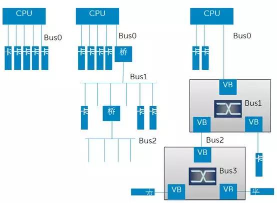
The generation before PCI-E was the PCI-X standard, which did not have the concept of a Switch. Fanout was achieved through bridging, forming a tree structure, as shown in the middle of the diagram above. The concept of a Switch was introduced in the PCI-E era. Its most fundamental difference from a bridge is that multiple roles within the same Bus communicate via Switch-based exchange rather than a shared bus. The PCI-X era truly used a shared bus for data transfer, which implied arbitration and low efficiency. However, PCI-E retained the basic concepts of the PCI-X architecture, such as continuing to use the terms "Bus" and "Bridge", but both of these roles became virtual. A Switch is equivalent to a collection of virtual bridges + virtual buses. Each Virtual Bridge (VB) can only connect to one End Point (EP) device (i.e., the final device/card) or cascade to another Switch, but not to a bus, because the physical bus no longer exists. This form of fanout must still adhere to a tree structure because a tree structure is the simplest, has no loops, and does not require complex routing considerations.
2. Partition The partitioning function is analogous to VLANs in an Ethernet Switch or Zones in a SAS Switch/Expander.
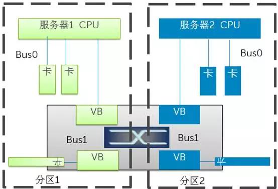
As shown in the diagram above, two or more machines can connect to the same PCI-E Switch. Partitioning is configured on the Switch to assign certain EP devices to a specific server. This allows for unified management and flexible allocation. Each server's BIOS or OS will only discover the virtual bridges, virtual buses, and EPs assigned to it when enumerating the PCI-E bus. Multiple partitions operate independently without interference. If multiple independent servers are connected to the same Switch without partitioning, problems will arise, because both OSs will independently enumerate the same set of PCI-E bus roles and assign access addresses to them, leading to conflicts.
3. NTB In some special scenarios, such as multiple controllers in traditional storage systems, they need to synchronize a lot of data and control information and wish to communicate directly using PCI-E links. The problem is that the two servers in the diagram cannot communicate directly because they must be in two different partitions. To meet this requirement, NTB (Non-Transparent Bridge) technology emerged. Its basic principle is address translation, because two different systems (termed System Images, SI) each have their own address space, which can overlap. Therefore, by performing address mapping and translation on the corresponding data packets within the PCI-E Switch, communication between the two parties can be achieved. This bridging technology with address translation is called a Non-Transparent Bridge.
![](https://pub-048dcb96257f476697b113fcb5939cb9.r