【Chinese-made AI Servers】Fully Domestic PCIe 4.0/5.0 Switch GPU Expansion Solution, Supporting Platforms like Hygon/Phytium/Loongson
Foreword:
A significant portion of the PCIe specification is dedicated to PCIe switches. In practical circuit applications, we often encounter scenarios where the number of PCIe ports is insufficient, requiring a switch to expand them.
Currently, only Broadcom and Microchip offer PCIe Gen5-capable switches. Broadcom's PEX8900 series was released earlier, supporting PCIe Gen5 speeds, and offering both base switch mode (fanout expansion mode) and synthetic switch mode. I have experience with Broadcom's PEX89144 and PEX89104. In the practical application section below, I will focus on the considerations for PEX89144. Diodes' PI7C9X2G1616PR and Microchip's PM8536 will also be briefly analyzed.
As a hardware developer, before delving into switches, it's essential to understand certain concepts from the PCIe specification. Taking Broadcom's PEX8724 as an example, parameters such as DMA, PCIe Lane/Port, transmission latency, and NT functionality must be understood to make correct switch IC selection and design decisions.
Chinese-made PCIe 4.0/5.0 Switch GPU Expansion Solution, supporting platforms like Hygon/Phytium/Loongson. Shenzhen Xinmai provides fully domestic backplane customization services.
I. PCIe Protocol - Switch-Related Knowledge Points
Before selecting a PCIe switch, it's necessary to familiarize yourself with the following switch-related knowledge points from the PCIe Base Specification:
1. What is a switch:
Protocol defines Switch: A defined System Element that connects two or more Ports to allow Packets to be routed from one Port to another. To configuration software, a Switch appears as a collection of virtual PCI-to-PCI Bridges.
Concept of a Switch: A switch is a collection of virtual PCI-to-PCI Bridges that connects two or more Ports and allows packets to be routed from one Port to another.
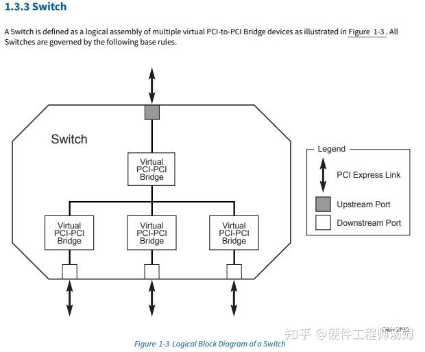
Figure 1
2. Switch application modes:
- Fanout Expansion Mode
- Partitioning Mode
- NTB (Non-Transparent Bridge)
a, Fanout Expansion Mode is the simplest. The fanout configuration follows a tree structure, which is the simplest because it has no loops and does not require complex routing considerations. Figure 2 illustrates the fanout mode.
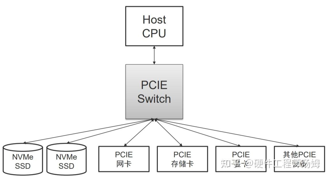
Figure 2
b, Partitioning Mode. The partitioning function is analogous to VLANs in an Ethernet Switch or Zones in a SAS Switch/Expander. Two or more machines can connect to the same PCI-E Switch. The switch is configured to partition and assign specific EP (Endpoint) devices to a particular server. This allows for centralized management and flexible allocation. When each server's BIOS or OS enumerates the PCI-E bus, it will only discover the virtual bridges, virtual buses, and EPs assigned to it. Multiple partitions operate independently without interference. If multiple independent servers are connected to the same switch without partitioning, problems will arise because two OSes will separately enumerate the same set of PCI-E bus roles and assign access addresses, leading to conflicts.
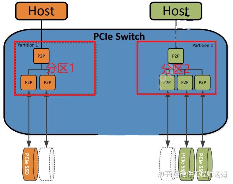
Figure 3
c, NTB (Non-Transparent Bridge). In some special scenarios, such as multiple controllers in traditional storage systems that need to synchronize a lot of data and control information, direct communication via a PCI-E link is desired. The problem is that the two servers in the diagram cannot communicate directly because they must be in two different partitions. To meet this requirement, NTB technology emerged. Its basic principle is address translation, as two different systems (termed System Images, SI) each have their own address spaces, which overlap. Therefore, by performing address mapping and translation on the corresponding data packets within the PCI-E Switch, communication between the two parties can be achieved. This bridging technology with address translation is called a Non-Transparent Bridge.
Figure 4 below shows the upstream ports in two partitions configured as NTB, allowing the two HOSTs to access devices under each other's partitions.
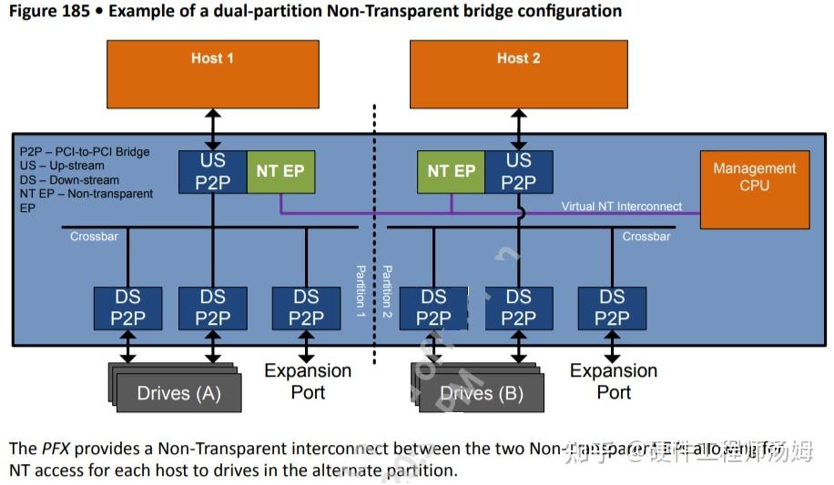
Figure 4
Figure 5 below explains the propagation path of TLPs under NTB:
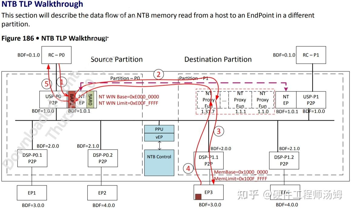
Figure 5
3. What is the difference between PCIe Link, PCIe Port, and PCIe Lane?
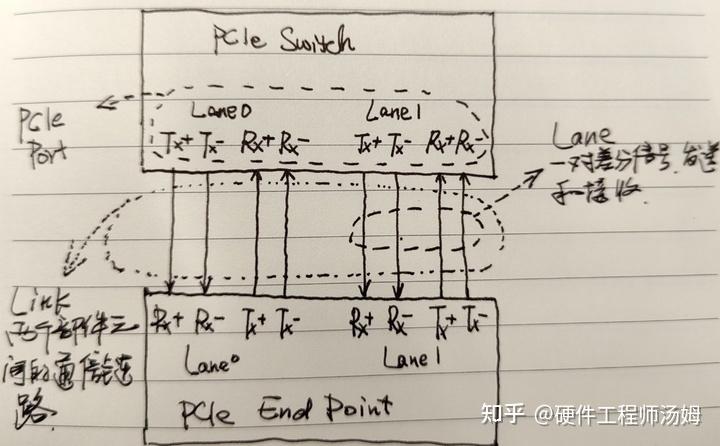
Figure 6
- Concept of a Link: A collection of two Ports and the Lanes connected between them. A Link is a dual-simplex communication channel between two components. (Protocol definition: A Link represents a dual-simplex communications channel between two components. The fundamental PCI Express Link consists of two, low-voltage, differentially driven signal pairs: a Transmit pair and a Receive pair.)
- Lanes refer to the physical channels in the PCIe bus, with each Lane consisting of a pair of TX and RX differential signal pairs. (Protocol definition: each Lane represents a set of differential signal pairs (one pair for transmission, one pair for reception)). Each Lane in the PCIe bus is an independent, full-duplex channel that can support a certain data transfer rate. The PCIe bus version number, as well as the rate and number of Lanes supported by each version, are defined by the Lanes. For example, PCIe 3.0 x16 indicates 16 Lanes, with each Lane having a data transfer rate of 8 GT/s.
- Port: Logically, it is an interface between a component and a PCIe link; physically, it is a group of Transmitters and Receivers located on the same chip that define a link. (Protocol definition: logically, an interface between a component and a PCIE link; Physically, a group of Transmitters and Receivers located on the same chip that define a link.)
In summary: Each Port contains multiple Lanes, and the different PCIe bus transfer rates and number of Lanes determine the total bandwidth of each port.
4. Store-and-Forward Switching vs Cut-Through Switching
- Store and Forward is easy to understand: the Switch receives the entire packet, processes it, and if there are no errors, it forwards it to the destination port. If there are errors, it requests the sender to retransmit according to the ACK/NAK protocol. The advantage of this method is ensuring that only correct packets are sent to the egress port, preventing wasted egress port bandwidth. The disadvantage is obvious: it increases packet latency within the Switch.
- To reduce latency, the specification defines another transmission method called Cut-Through. Similar to Cut-Through mode in Ethernet, the Switch begins forwarding the packet to the destination port as soon as it receives the packet header, without waiting for the entire packet to be received. This mode significantly reduces packet latency within the Switch, although if a packet has errors, it will waste egress port bandwidth. Overall, link packet errors are a minority, and this mode is generally superior.
Figure 7 below shows the explanation of cut-through mode in Broadcom's PEX8733:
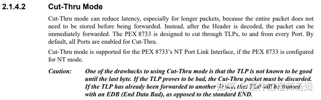
Figure 7
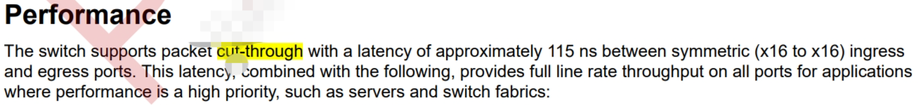
Broadcom's PEX8733 has a maximum cut-through latency of 132ns.
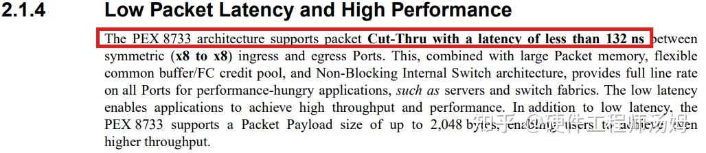
Figure 8
Broadcom's PEX89144 has a cut-through latency of approximately 115ns.