Urban Rail Transit: Overall Design of a Domestically Developed Onboard Central Control Unit Based on Hot Backup Technology (Part 1)
Overview
It is responsible for managing communication between nodes on the vehicle bus, processing information exchange between coupled locomotives, real-time status detection of control units and data acquisition and output units, intelligent diagnosis of locomotive control system faults, and automatic identification and processing of coupled locomotive formations.
Management of Communication Between Nodes on the Vehicle Bus
Node devices on the vehicle bus include intelligent display units, logic control units, microcomputer control cabinets, locomotive safety information integrated monitoring devices, as well as analog input/output boards, digital outputs, digital inputs, and so on. Communication among these node devices is managed by the central control unit.
When a node device on the bus fails, it generally does not affect the communication of other devices, but the entire locomotive will lose some or all functions of that device.
Information Exchange Processing Between Coupled Locomotives
Control commands from the driver's cab are acquired by the central control unit and transmitted via the vehicle bus to the relevant control units of the current vehicle. These commands are then transmitted via the inter-vehicle bus to the central control unit of other coupled vehicles, which in turn transmits them to the relevant control units within those vehicles. Status information of devices in each vehicle is transmitted in the opposite direction via the same vehicle bus and inter-vehicle bus to the central control unit for aggregation and processing. On one hand, this information is used for corresponding locomotive control logic processing, and on the other hand, it is displayed on the driver's console fault display screen or microcomputer display screen for observation and reference by drivers or maintenance personnel.
Real-time Status Detection of Control Units and Data Acquisition and Output Units
Real-time detection is performed on the operating status of various node devices and data acquisition and output units. When a fault occurs, it is diagnosed, saved, and displayed on the microcomputer display screen.
Intelligent Diagnosis of Locomotive Control System Faults
Each intelligent station continuously monitors important parameters. If an abnormality is detected, it triggers a fault data recording mechanism. Simultaneously, it reports to the higher level via the train communication network and is aggregated in the central control unit. The central control unit is equipped with a fault database for the entire vehicle. The stored information mainly includes the time of fault occurrence, location of fault occurrence, type of fault, and environmental parameters for a period before and after the fault occurrence. Maintenance personnel can retrieve this information using portable test tools. Based on the aggregated faults, an evaluation is made, and fault information is displayed to the driver via the display unit, along with information regarding the overall operational capability of the train.
Automatic Identification and Processing of Coupled Locomotive Formations
Locomotives can be re-formed to a certain extent, and re-formable locomotives are connected via a communication link. After locomotives are re-formed, the central control unit can re-allocate address space for the re-formed locomotives.
Objective of Implementing Dual-Machine Hot Backup
The central control unit of the original electric locomotive adopted a manual cold backup method to achieve reliability and fault redundancy design. This implementation method has various drawbacks and inconveniences. Table 1 compares hot backup and manual cold backup methods.
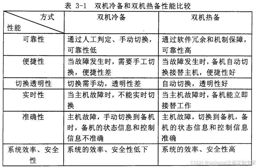
Due to the various drawbacks and disadvantages of using cold backup, its low reliability and inefficiency in fault handling and judgment mean that operational safety cannot be guaranteed when the main unit fails, and real-time control information and data cannot be recovered in a timely manner. Therefore, implementing hot backup in the design is highly necessary.
Prerequisites for Implementing Dual-Machine Hot Backup
The main prerequisite for the backup unit to seamlessly take over locomotive control is that, when a switchover occurs, the backup unit must have the same status data and control information as the main unit at the moment immediately preceding the fault. This ensures high real-time performance and security for system control and transmission, and maximizes operational safety.
Goals and Principles for Dual-Machine Hot Backup Design
Considering these prerequisites, implementing hot backup for the central control unit under train network conditions requires considering the following factors:
Accuracy: When the main unit fails, the backup unit must be able to automatically alert and take over control. The status and control information of the backup unit should be consistent with that of the main unit immediately before the fault, achieving true data synchronization.
Real-time Performance: Control and status information between the main unit and backup unit must be communicated in real-time. When the main unit fails or recovers, the communication mechanism must ensure that other relevant devices can promptly acquire information and determine communication targets.
Convenience: Control switchover between the main unit and backup unit must be completed automatically. Fault status judgment for either the main or backup unit must also be automatically performed.
Interchangeability: During normal operation, the main and backup units can alternate their work at a certain frequency, thereby achieving higher reliability.
Key Technical Challenges in Implementing a Dual-Machine Hot Backup System
The key technical challenges in implementing hot backup for the central control unit are, firstly, determining when to switch over, i.e., defining the switchover criteria; and secondly, how to achieve seamless switchover while maximizing operational safety. Seamless switchover requires that, at the moment of switchover, the main and backup units have identical control and status information from the moment immediately preceding the fault, as well as synchronized inputs and outputs.
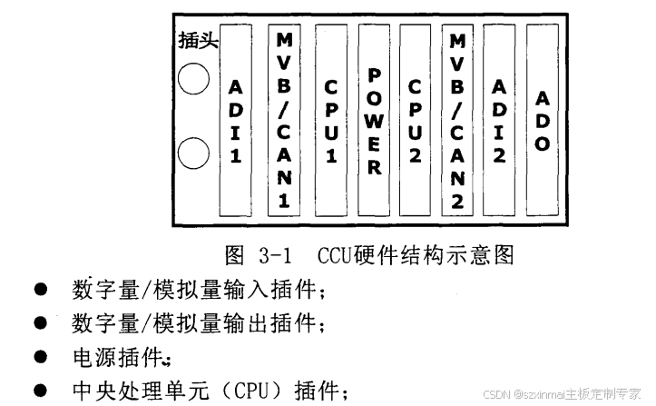
System Hardware Architecture
According to requirements, the system can be divided into the following functional modules, as shown in Figure 1.