【Rail Transit】Analysis of Fault Causes and Domestic Replacement for Locomotive Central Control Units
Overview of the Central Control System
Hohhot Group Corporation in northern China experienced a locomotive upgrade and replacement, with SS4 modified electric locomotives being replaced by HXD2 high-power locomotives, which are now widely deployed. TCMS is the microcomputer network control system for these locomotives. Its network architecture consists of the Central Control Unit (MPU), Remote Input/Output Module (RIOM), Traction Control Unit (TCU), Auxiliary Control System (ACU), Brake Control Unit (BCU), and Driver Display Unit (DDU). The MPU chassis is installed in a microcomputer cabinet within the locomotive's equipment compartment. The microcomputer cabinet is divided into three layers: the bottom layer houses electrical wiring harnesses and circuit breakers, the middle layer contains the Remote Input/Output Module (RIOM2), and the top layer contains the Central Control Unit (MPU) chassis and the GW Gateway Module. The microcomputer cabinet does not have a ventilation system installed, and the MPU also relies on natural convection for ventilation and cooling, meaning there is no dedicated cooling fan, nor are there obvious vents for ventilation and heat dissipation. Routine equipment maintenance has revealed severe dust accumulation on the equipment inside the microcomputer cabinet.
2 Main Technical Parameters
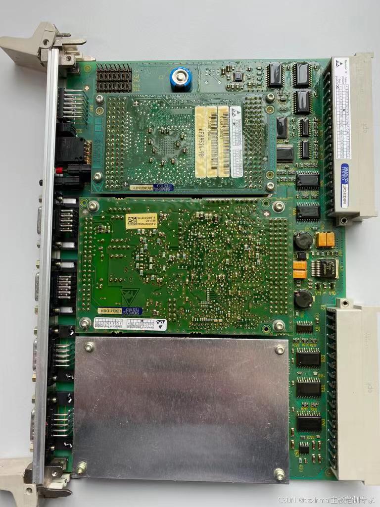
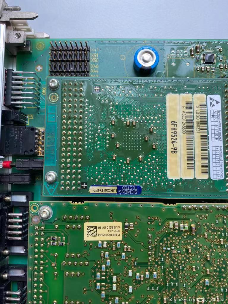
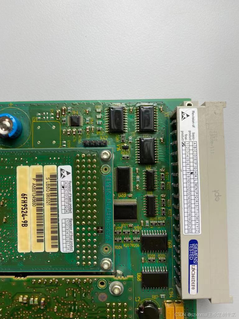
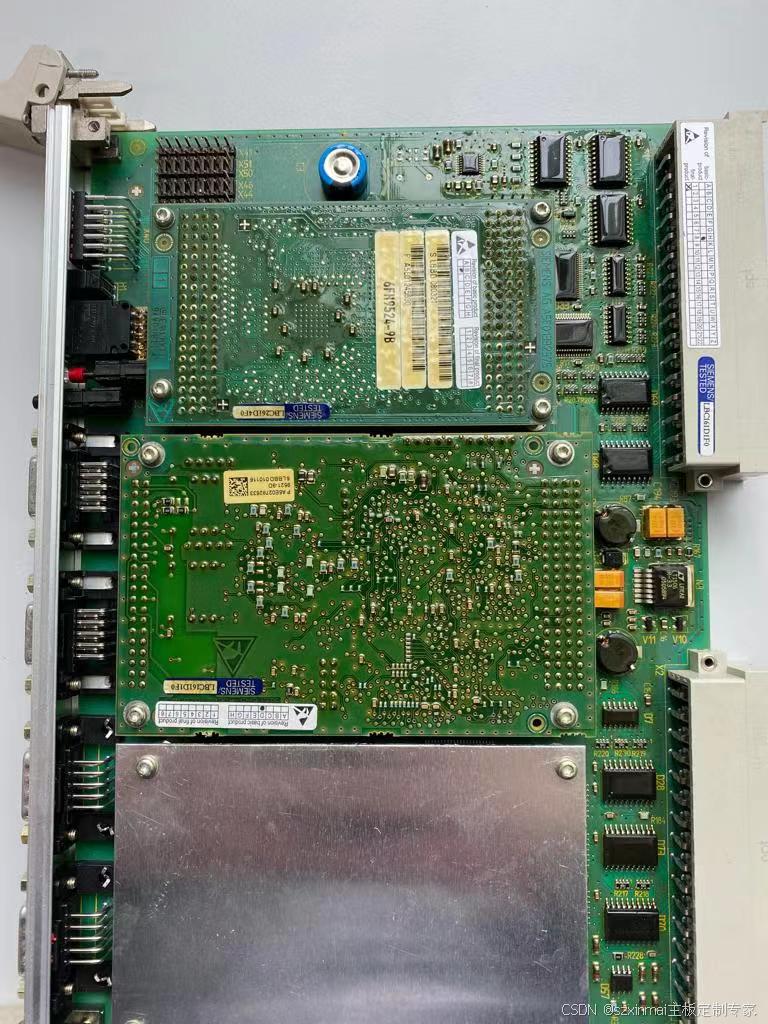
The MPU chassis power supply is 110V DC; the power consumption of each MPU chassis is less than 150W; the ambient temperature range is -40℃ to +70℃. The MPU chassis has 8 plug-in boards: ① Chassis Power Board; ② External Sensor Board; ③ FIPV Network Communication Board; ④ Serial Interface Board; ⑤ FIPT Network Communication Board; ⑥ CPU Board; ⑦ Analog Input/Output Board; ⑧ Maintenance Board. The MPU chassis has a total of 6 indicator lights: 1st, 2nd positions: System power-on indicator (Lit: Normal; Off: Not powered on); 3rd position: PLC running indicator (Flashing: Normal; Not flashing: Abnormal); 4th position: System software startup complete indicator (Flashing: System software startup complete; Not flashing: Startup not complete); 5th position: Configuration file normal (Flashing: Configuration file normal; Not flashing: Configuration file error); 6th position: USB dump and recording task indicator (USB drive inserted, flashing indicates file dumping in progress, off indicates dump complete; USB drive not inserted, light flashing indicates task recording fault, not flashing is normal).
3 Working Principle
The role of the MPU on the locomotive is to serve as the command and control center for the entire locomotive. It consists of two identical redundant units, MPU1 and MPU2, similar to the left and right brain systems in humans. One unit is responsible for commanding and supervising equipment, and the other is responsible for recording equipment status data. The two units are designed with redundancy. After the locomotive's onboard equipment starts, it automatically detects and identifies the devices. The first one identified becomes the master control unit, and the other unit defaults to the slave control unit, operating in hot standby mode. Only when the master control unit fails to respond within the specified time will the slave control unit switch from hot standby to master control, taking over the locomotive control system. Alternatively, if the master control unit suddenly fails while the locomotive is operating on the line, the hot standby master control unit will take over the control system, ensuring continued stable operation. The MPU communicates and exchanges information with other devices via the TNC network and processes various information provided by the network to achieve information processing, monitoring, and recording of locomotive operation.
4 Fault Data Analysis and Reasoning During Operation
During the online operation of HXD2 locomotives, differences in operating regions and seasonal environmental changes have led to hardware, software, and network faults in some key locomotive components, also revealing some design flaws in the locomotive. The climate in central and western Inner Mongolia in summer is characterized by high temperatures, dry air, and strong solar radiation. This season presents the harshest internal working environment for locomotives and is a test period for their quality. Taking the MPU fault as an example, we conducted an analysis and reasoning of the fault data.
During the operation of locomotive No. 01, an MPU1 fault occurred in Section A. We downloaded and analyzed the MPU data, which showed the fault occurred at 14:45 on July 21st. The MPU1 communication signal abnormally stalled, communication was lost, and MPU2 intervened and took over MPU1 as the master control unit. At this point, MPU1 became the slave control unit. Later, the locomotive closed the main circuit breaker and continued operation. During this period, MPU1's communication signal naturally recovered and it re-intervened to become the master control unit, causing a command conflict with MPU2, which led to the locomotive's main circuit breaker tripping again. During maintenance, it was noticed that the temperature inside the locomotive's equipment compartment was high, and some components felt hot to the touch. We conducted a detailed inspection and verification of the MPU1 chassis and its wiring, finding no abnormalities. The chassis indicator lights flashed normally, and high-voltage tests were repeatedly performed, all showing normal results.
To find the cause, we decided to swap the MPU chassis with that of locomotive No. 02 for operational tracking. It was found that the same chassis fault still occurred occasionally on locomotive No. 02. Faults mostly occurred in the afternoon, and the MPU chassis would return to normal after being shut down for a period.
On July 24th, locomotive No. 03 experienced the same fault again. The cause of the fault was: MPU1 fault in Section A's master control unit. During maintenance after the locomotive was taken out of service and returned to the depot, we downloaded and analyzed the MPU data. The data showed that at 15:32 on July 24th, the locomotive's main circuit breaker tripped. MPU1's heartbeat signal, which is a normal cyclic variable, stalled and was lost. At this point, MPU1 was isolated, and MPU2 took over as the master control unit. MPU1 remained in an isolated state for a long time. During maintenance, the equipment compartment was stuffy and hot, and MPU1 was found to be burnt out. After replacing the MPU chassis equipment, the locomotive operated normally. Over approximately 40 days, this fault occurred a total of 8 times.
5 Cause of Fault
Continuous faults occurred in the MPU chassis during locomotive operation. We believe that the degradation of component performance caused by high temperatures in the MPU chassis is the direct cause of the faults. After summarizing the fault conditions of the locomotives, it was found that the fault time data was consistent, the fault phenomena were identical, all occurred during the daytime, and the weather conditions were dry and hot. The MPU's operating system itself is a multi-tasking real-time operating system. The chassis's operating ambient temperature is -40℃ to +70℃. Under conditions of high temperatures and prolonged online operation, when locomotive ventilation is poor, the internal temperature of the equipment compartment can reach approximately 36℃ to 40℃. The surface temperature of some internal electrical components can reach nearly 55℃. The microcomputer cabinet has no obvious vents, relying on natural convection for ventilation, resulting in poor heat dissipation. The MPU chassis also lacks a dedicated ventilation and heat dissipation system. Furthermore, prolonged power-on during hot weather leads to excessive temperature rise inside the working chassis, causing degradation of internal component performance, poor stability, and ultimately MPU faults.
Addressing the poor ventilation, heat dissipation, and high temperature issues of the MPU chassis, we decided to install an independent ventilation and heat dissipation unit on the MPU chassis to create an effective ventilation and cooling circulation system. This aims to improve the working environment quality and ensure system operational stability. Since the microcomputer cabinet contains only electrical components and wiring, a filtering system was added to the radiator's air outlet. After installation, we tracked data for locomotives No. 01, 02, and 03. Long-term data accumulation showed that the MPU was operating in good condition with normal data. Locomotive operational stability significantly improved, and operating efficiency reached high standards.
6 Conclusion
Microcomputer network control systems are playing an increasingly important role in ensuring the quality of locomotive operation. The stability of each control unit in the locomotive is the cornerstone of safety. Quality issues concerning integrated modules of electrical components, locomotive network communication systems, and other major control systems are paramount in maintenance. Accurate analysis and summarization of operational data have also played a pioneering role in eliminating potential fault hazards. Strengthening daily equipment maintenance, performing targeted preventive maintenance based on seasonal changes, and conducting diligent and detailed inspections have become the mainstream approach in locomotive maintenance.
Shenzhen Xinmai provides domestic locomotive control system board solutions.