AM64X+FPGA-Based Control and Protection Solution for UHV Power Transmission, Supporting VXWORKS
AM64X+FPGA-Based Control and Protection Solution for UHV Power Transmission, Supporting VXWORKS
Specification
Description
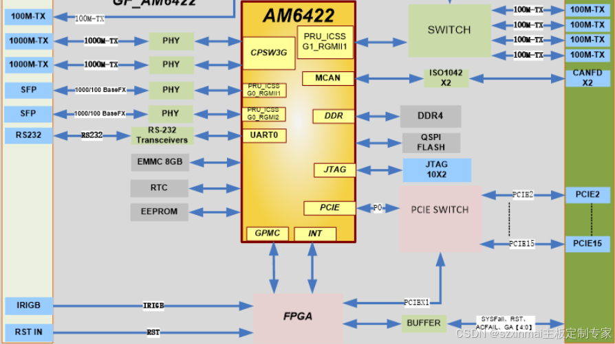
Processor
1 Dual-core 64-bit Arm Cortex-A53 at up to 1.0GHz
Operating System
LINUX, VXWORKS
Storage
2GB DDR4, 8GB EMMC, QSPI
Interfaces
• 2x 10/100/1000 Mbps ETH
• 5x 10/100Mbps ETH
• 2x 100/1000 Base-FX
• 1x IRIGB
• 2x CANFD
• 1x Debug RS232
• 15x PCIe
• IRIGB
Debug Interface
JTAG / COP debug port
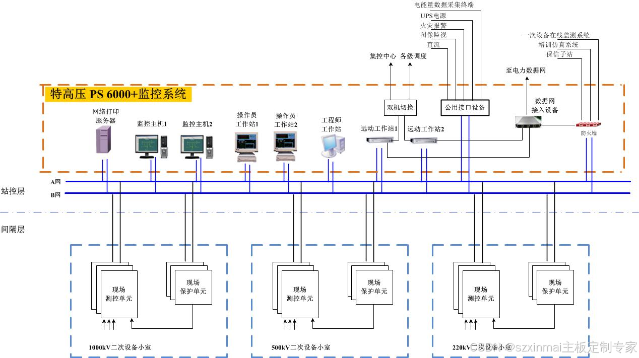
UHV Transmission and Substation Monitoring System Architecture Diagram
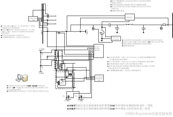
UHV Protection Device Schematic Diagram
Technical Advantages
Main Equipment Typical Configuration Table
Category
Type
Main Functions and Features
Monitoring
Measurement & Control
Real-time acquisition, processing, and transmission of primary equipment sensor data;
Achieves data acquisition for digital inputs/outputs, AC quantities, DC quantities, temperature signals, etc.;
Receives external operation commands for real-time control of primary equipment such as circuit breakers and transformer tap changers;
Features bay-level five-prevention interlock and synchronization check functions;
Unit-oriented, flexible configuration;
Communicates with station control level monitoring hosts, communication gateways, and other devices using IEC 61850-8-1;
Communicates with process level intelligent terminals and other devices using IEC 61850 GOOSE;
Supports IEC 61850-9-2 for communication with process level MUs.
Data Communication Gateway
Facilitates communication between the substation and master station systems (e.g., dispatch, production), providing data, models, graphics, and file transfer services for master station functions such as substation monitoring and control, information query, and remote browsing.
* Direct SCADA data acquisition and transmission
* Direct alarm transmission
* Supports remote browsing
* Supports source-side maintenance
* Supports dispatch (control) center requests for protection information and control of protection devices
* Supports remote operation and control of auxiliary equipment
Substation Operation Monitoring
* Operation and monitoring of station equipment
* Operation and control
* Anti-misoperation interlocking
* Sequential control
* Automatic voltage and reactive power control
* Intelligent operation tickets
* Topology live coloring
* Fault reconstruction
* Data identification
* Intelligent alarming
* Event recording and processing
* Equipment status monitoring and parameter query
Integrated Applications
* Integrated display of primary equipment online monitoring
* Secondary equipment status monitoring
* Auxiliary equipment status monitoring
* Comprehensive fault analysis
* Operation and maintenance management
Data Server
Achieves centralized storage of panoramic data for UHV transmission and substations;
Provides unified data query and access services for various applications.
Protection
Line
* Complies with Q/GDW 1161 "Standardized Design Specification for Line Protection and Auxiliary Devices"
* Integrated main and backup protection with overvoltage remote trip function, fully supporting IEC 61850
* Innovatively developed adaptive recognition criteria for faults and overloads, preventing maloperation of distance protection under overload conditions
* Employs a differential protection algorithm based on the Bergeron model, fully compensating for capacitive current including transients, solving the problem of large capacitive currents in UHV lines
Circuit Breaker
* Complies with Q/GDW 1161 "Standardized Design Specification for Line Protection and Auxiliary Devices", fully supporting IEC 61850
* Adopts CT tailing adaptive recognition criteria, solving the problem of large decay time constants during UHV line faults and improving the reliability of breaker failure protection
Transformer
* Complies with Q/GDW 1175 "Standardized Design Specification for Transformer, High-Voltage Shunt Reactor, and Busbar Protection and Auxiliary Devices"
* Includes multi-principle differential and backup protection, a single device can implement a complete set of electrical quantity protection functions for transformers, supporting DL/T 860 communication
* Adopts the sampled value differential principle based on waveform comparison, and inrush current blocking technology based on inverse-time DC compensation, solving the problems of frequent maloperation of transformer no-load energization protection and the influence of main transformers on tap-changing compensation transformers and inrush currents.
Busbar
l Complies with Q/GDW 1175 "Standardized Design Specification for Transformer, High-Voltage Shunt Reactor, and Busbar Protection and Auxiliary Devices"
l Features differential protection and breaker failure protection functions, fully supporting IEC 61850 communication
l Employs new anti-CT saturation measures such as "differential current dynamic memory method" and "trajectory scanning method" to ensure no maloperation during external busbar faults with CT saturation, and reliable operation when an internal fault occurs or an external fault transitions to an internal fault.
* Pioneered the patented technology "Busbar Protection Fast CT Disconnection Judgment Scheme Based on Current Change Rate", which quickly identifies CT disconnection and solves the problem of differential protection maloperation during CT disconnection in heavily loaded feeders.
Low Voltage Integrated Protection and Measurement
* Full range of low-voltage line, transformer, capacitor, reactor, bus coupler protection, and automatic transfer switch for backup power;
* Unified hardware and software platform design, supporting assessment and metering functions;
* Connects to low-voltage primary equipment via cables, can also be configured to communicate with process level MUs, supporting IEC 61850-9-2;
* Supports communication with bay level devices via the station control level network, using IEC 61850 GOOSE;
* Communicates with substation monitoring, data communication gateways, protection fault information sub-stations, and other devices using IEC 61850-8-1.
Network Communication
Network
The substation internal communication network is composed of high-speed Ethernet, with a transmission bandwidth greater than or equal to 100Mbps;
Central switching connections can use 1000Mbps data port interconnection;
The network can be segmented into different logical segments by dividing Virtual Local Area Networks (VLANs).
Switch
Complies with the application requirements of smart substations;
Industrial-grade Ethernet switches that perform frame forwarding and filtering using MAC address addressing at the data link layer.
Information Security
Firewall
The firewall is located between Substation Security Zone I (Real-time Control Zone) and Security Zone II (Non-control Production Zone), implementing logical isolation, packet filtering, and access control functions between the two zones.
Unidirectional Security Isolation
Power-specific horizontal unidirectional security isolation devices are essential boundary protection measures between the substation's production control domain and management information domain, providing isolation strength equivalent to physical isolation;
Classified into forward-type and reverse-type according to data communication direction;
Forward-type security isolation devices are used for non-network unidirectional data transmission from the production control domain to the management information domain;
Reverse-type security isolation devices are used for unidirectional data transmission from the management information domain to the production control domain, serving as the sole data transmission path from the management information domain to the production control domain;
The smart substation monitoring system transmits data to the Zone III/IV data communication gateway via forward and reverse isolation devices, enabling information transmission with other Zone III/IV master stations.
Vertical Encryption and Authentication
Vertical encryption and authentication employs technical measures such as authentication, encryption, and access control to achieve secure remote data transmission and vertical boundary protection. When the smart substation monitoring system communicates data with the remote dispatch (control) center, it uses vertical encryption devices to build a vertical security protection system.
Main Equipment Typical Configuration Table
No.
Type
Content
Model
Quantity
Unit
I. Station Control Level
1
Monitoring
Monitoring Host
Domestic Server (Unix/Linux/Windows)
2
Sets
Operator Workstation
Domestic Server (Unix/Linux/Windows)
2
Sets
Engineer Workstation
Domestic Server (Unix/Linux/Windows)
1
Set
Data Server
Domestic Server (Unix/Linux/Windows)
1
Set
Monitoring System Application Software
PS6000+
—
Sets
2
Communication Gateway
Zone I Data Communication Gateway
PSX 681/PSX 610G
2
Units
Zone II Data Communication Gateway
PSX 681/PSX 610G
2
Units
Zone III/IV Data Communication Gateway
PSX 681
1
Unit
3
Printer
Printer
—
1
Unit
4
Time Synchronization
Time Synchronization Device
—
1
Set
5
Information Security
Firewall
Nationally Certified Equipment
2
Units
Forward Isolation Device
Nationally Certified Equipment
2
Units
Reverse Isolation Device
Nationally Certified Equipment
2
Units
6
Communication Equipment
Station Control Level Switch
—
—
Units
Modem
—
2
Units
II. Bay Level
7
Measurement & Control
Line Measurement & Control
PSR 660U Series
—
Units
Circuit Breaker Measurement & Control
PSR 660U Series
—
Units
Transformer Measurement & Control
PSR 660U Series
—
Units
Busbar Measurement & Control
PSR 660U Series
—
Units
Common Measurement & Control
PSR 660U Series
—
Units
8
Protection
High Voltage Line Protection
PSL 600U Series
—
Units
Circuit Breaker Protection
PSL 630U Series
—
Units
Transformer Protection
PST 1200U Series
—
Units
Busbar Protection
SGB 750 Series
—
Units
Medium Voltage Line Protection (incl. integrated protection & measurement)
PSL 620U Series
—
Units
Medium Voltage Transformer Protection
PST 671U Series
—
Units
Low Voltage Side Integrated Protection and Measurement Device
PS 640U Series
—
Units
9
Fault Recorder
Fault Wave Recorder
DRL 600 Series
—
Sets
10
Communication Equipment
Bay Level Switch
—
—
Units