【ARM+Codesys Customer Case】Electroplating Production Line Solution
1 Introduction to Electroplating Production
Electroplating is a crucial process. Products treated with electroplating not only achieve improved quality but also significantly enhanced performance, while extending their service life. An electroplating production line refers to a complete system that integrates various related components according to specific electroplating process requirements. These components include electroplating treatment tanks, electroplating hoist movement devices, power supply equipment, circulation and filtration units, testing instruments, heating devices, air agitation devices, drainage systems, and pollution treatment units, all coordinated and controlled by an electrical control system. Automatic electroplating production lines reduce material consumption, lessen human labor intensity, minimize human contact with chemical pollutants, and simultaneously improve production efficiency and quality. They also facilitate the digital and centralized management of equipment and production processes. The operation of the hoist and the temperature of the electroplating system directly impact product quality and efficiency. The core control solution utilizes Hecuan's Q-series advanced motion controller, developed based on CODESYS software. Combined with Hecuan's X3EB EtherCAT servo system, it achieves high-speed, high-precision, and flexible movement of various plated parts. Simultaneously, PID algorithms enable rapid, stable, and reliable response for system temperature control.
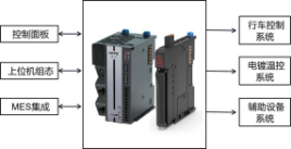
Figure 1 Electroplating Control System Framework
2 Basic Workflow of an Electroplating Production Line
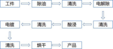
Figure 2 Electroplating Production Process Flow
The production stages of an automatic electroplating line are generally divided into three phases: pre-plating treatment, electroplating process, and post-plating treatment. Pre-plating treatment is the preparatory stage for electroplating, involving surface preparation of the workpiece before plating. Its main purpose is to remove metal oxide layers or oil stains from the workpiece surface, thereby reducing impurities during electroplating and ensuring the quality of the plating layer. Generally, pre-plating treatment processes primarily include degreasing, electrolytic degreasing, electropolishing, electro-etching, activation, and rinsing. The electroplating process involves placing the workpiece into a plating tank for electroplating. The most crucial aspects are controlling the plating solution's temperature, voltage, current, and plating time, which can last several hours. Post-plating treatment primarily involves chromium-containing rinsing to ensure the quality of the electroplating.
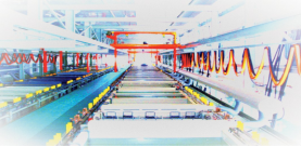
Figure 3 Schematic Diagram of an Electroplating Production Line Site
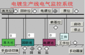
Figure 4 HMI Visualization Interface for the Electroplating Production Line
3 Electrical Configuration and Control Description of the Electroplating Production Line
The electrical configuration is shown in Figure 5. The hoist primarily consists of a lifting servo motor for vertical movement of workpieces and a translational servo motor for horizontal movement. The positioning of these servos is mainly achieved using the MC_MoveAbsolute absolute positioning function provided by CODESYS. According to process requirements, the servo-driven mechanisms complete cleaning in the rinsing tanks and electroplating in the plating tanks, combining various stations to ultimately complete the electroplating process for the workpiece.
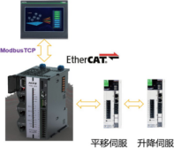
Figure 5 On-site System Topology of Electroplating Production Equipment
The system offers two control modes: manual and automatic. Automatic control is further divided into single-cycle and continuous control. Subroutines are used for programming, with the main program handling system initialization and subroutine calls. The times for electroplating, recovery, and cleaning can be set and modified on the touchscreen based on different workpieces and ambient temperatures, achieving optimal control, ensuring product quality, and improving work efficiency.
4 PID Temperature Control Process for Electroplating Production Line
PID control is widely used in closed-loop control systems due to its advantages: it does not require a mathematical model of the controlled object, has a simple structure, is easy to implement, offers strong flexibility and adaptability, and is convenient to use. For controlling the temperature of the plating bath solution, it is first necessary to overcome the effects of varying object characteristics, nonlinearity, noise, asymmetric gain characteristics, and significant pure lag, to achieve relatively precise temperature control. During electroplating, the temperature of the plating bath solution should be controlled within a specific range to ensure fine and uniform plating layer crystallization. Therefore, in this example, PID control is used to maintain a stable temperature of the controlled object, meeting production process requirements and ensuring electroplating quality. When performing PID control of analog quantities using Hecuan's Q0 PAC, developed on the CODESYS software platform, the system function blocks provided by CODESYS can be utilized.
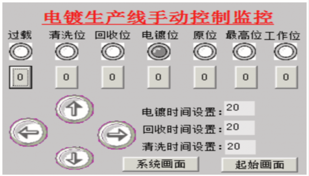
Figure 6 HMI Operation Interface for the Electroplating Production Line
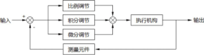
Figure 7 PID Control Schematic Diagram
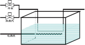
Figure 8 Schematic Diagram of Electroplating Tank Temperature Control
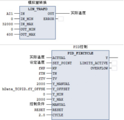
Figure 9 PID Temperature Control Implementation Program
PID (Proportional, Integral, Derivative) control is widely applied in temperature control due to its characteristics such as good robustness, ease of implementation, simple algorithm, strong flexibility, and high accuracy. PID has three key parameters: proportional coefficient KP, integral coefficient KI, and derivative coefficient KD. In the PID control algorithm, proportional (P) control is the simplest method, where the controller's output is proportional to the input error value (KP). As soon as an error occurs in the system, proportional adjustment immediately acts to reduce it. The integral (I) component is primarily used to eliminate steady-state error. Steady-state error refers to the difference between the output value and the setpoint after the system stabilizes. The integral component is essentially a process of accumulating errors, adding the accumulated error to the original system to counteract the steady-state error caused by the system. Derivative parameter: The derivative signal reflects the rate or trend of change in the error signal. Based on this trend, anticipatory adjustment is performed, thereby increasing the system's rapid responsiveness.
5 Conclusion
With the development of automation technology and industry, industrial equipment is becoming increasingly advanced and intelligent. Electroplating equipment production lines are also continuously innovating and evolving to a new stage, driven by the demands of upstream and downstream industries and the market. The maturity of the motion control industry and the prominence of cost-effectiveness have led to the increasing application of servo motors in various equipment. Their compact structure, high speed, high precision, ease of development and design for technical personnel, and strong adaptability are driving the deep integration of servo control systems with traditional industries, empowering traditional equipment towards intelligent upgrades. In the context of the electroplating industry, the on-site environment is often harsh, with various chemicals harmful to humans. The intelligence of equipment and the unmanned operation of entire production lines prevent direct human contact with hazardous environments. Furthermore, a high degree of automation improves product quality and production system efficiency, significantly reduces raw material consumption, achieving quality improvement, efficiency gains, cost reduction, and promoting human health.
Xinmai offers localized customization for ARM+Codesys.