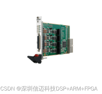
8-Channel Standard 3U PXIe Multifunction Asynchronous Serial Communication Isolated Card, Supports RS232/422/485 Modes, Max 10Mbps, Supports Virtual COM Port
8-Channel Standard 3U PXIe Multifunction Asynchronous Serial Communication Isolated Card, Supports RS232/422/485 Modes, Max 10Mbps, Supports Virtual COM Port.
Product Features
QC PXIe-7108
Number of Channels
8 Channels
Communication Modes
Supports RS232, RS422, RS485, DIP switch selectable
Signal Isolation Method
Input/Output Isolation
Baud Rate
RS232 MAX 1 Mbps
RS422/485 MAX 10 Mbps
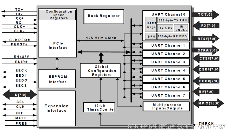
FIFO
256 MBytes Transmit and Receive FIFO
Data Format
Parity Bit: None, Even, Odd, Space, Mark
Data Bits: 5, 6, 7, 8
Stop Bits: 1, 1.5, 2
I/O Address/IRQ: BIOS Assigned
Connector
Port0-7: VHDCI68-1
PXIe_CLK100
Supported
Interface
PCI Express Gen1 X1
Serial Port Protection
Onboard 15 KV ESD Protection and Surge Protection
System Support
Windows2000/XP/2003/Vista/Win7/Win10, Linux 2.4/2.6
Software Support
LabVIEW, C, QT, etc.
Programming Method
Virtual COM Port, Supports Standard Serial Port Debugging Assistants
Electrical Characteristics
Voltage (V)
Current (Amps) Max
+3.3 V
0.3 A
+5.0 V
0.3 A
+12.0 V
0.0 A
-12.0 V
0.0 A
+5V AUX
0.0 A
Physical Characteristics
Module Dimensions
100*160mm
Slot Requirement
4HP, PXI Express
Compatibility
Fully Compatible with PXI Express 2.0 Specification
Weight
122g (Typical)
Environmental Characteristics
Shock
30g, Half-sine, 11ms Pulse Duration
Random Vibration
Operating: 0.3grms, 5~500Hz per axis, 3 axes
Non-operating: 2.46grms, 5~500Hz per axis, 3 axes
Operating Temperature Range
-20℃ ~ +55℃
Storage Temperature Range
-40℃ ~ +70℃
Card Topology
Pinout
The card integrates one VHDCI68 connector, J4 is for Ports 1-8; the VHDCI68 Pinout is as follows:
J4 68-Pin VHDCI Port 1-8
RS485
Signal
RS422
Signal
RS232
Signal
66
57
49
40
32
23
15
6
RS485-
RXD-
68
59
51
42
34
25
17
8
RXD
65
56
48
39
31
22
14
5
TXD
64
55
47
38
30
21
13
4
RS485+
RXD+
60
60
43
43
26
26
9
9
ISO_GND
ISO_GND
ISO_GND
63
54
46
37
29
20
12
3
62
53
45
36
28
19
11
2
61
52
44
35
27
18
10
1
TXD+
67
58
50
41
33
24
16
7
TXD-
Note:
- ISO_GND is the isolated ground; the serial port ISO_GND is isolated from the chassis power GND.
- After driver installation, Ports 1-8 will be assigned COM port numbers in ascending order.
RS232/422/485 Mode Configuration (Serial card factory default: RS232 mode)
The card provides 8 dual-position DIP switches, S1~S8, corresponding to Port1~Port8 respectively.
RS232 Wiring Diagram