Application of FPGA Core Board in Sonar Systems
Introduction
Sonar systems use sound pulses to detect, identify, and track underwater objects. A complete sonar system consists of a control and display unit, a transmitter circuit, a receiver circuit, and a transducer that functions as both an emitter (speaker) and a detector (high-sensitivity microphone).
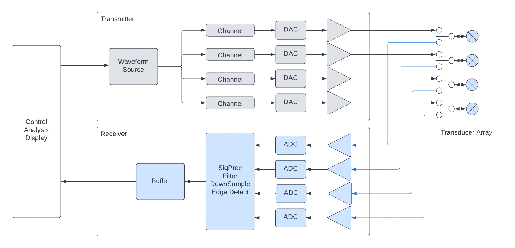
Sonar System Diagram
Technical Challenges
The sonar transmitter discussed in this article is a phased array transmitter capable of emitting frequencies from 10 kHz to 100 kHz. The system employs an array of transmitter modules, with each module capable of driving eight sonar transducers. The FPGA design incorporates several unique modules: an ARM processing unit (Intel HPS), a waveform generator, channel interfaces, clock and chip timing, system monitoring and control, and status registers.
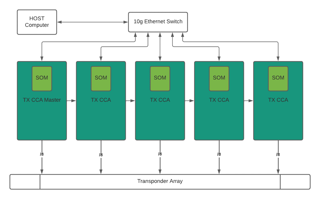
System Block Diagram
Solution
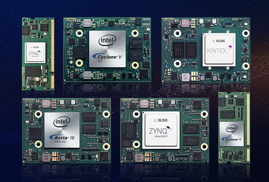
This project utilizes an Intel FPGA (Altera) Cyclone V-based core board. It supports a 64K-entry arbitrary waveform generator with scaling capabilities. Each core board controls eight channels of TX data. The waveform generator drives waveforms into eight instances of the channel module. The primary purpose of this module is to provide a unique programmable delay on a per-channel basis. Each PCB board features four dual-channel Digital-to-Analog Converters (DACs) from Analog Devices. The DACs accept data for each channel with the same data bits on alternating phases of the input clock. Additionally, a menu-driven build environment is provided, which includes a BSP to match the core board being used with one of several baseboards.
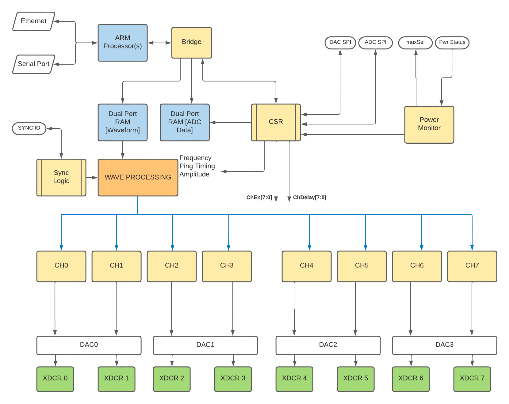
FPGA Top-Level Block Diagram
Conclusion and Next Steps
A conclusion drawn from this project is that a core board-based system design approach can save engineering time, allowing a team to more quickly begin testing and debugging their custom circuitry when they don't need to worry about the design and setup of the underlying SoC/FPGA. FPGA code and testing, as well as software development, can commence when the carrier board PCB design begins; once completed, transferring the core board and code to the new PCB is a straightforward process. The sonar transmitter described here includes portable code and has the potential for reuse in receiver designs.