Customized IRIG-B Time Synchronization Solution Based on AM62X + FPGA/MCU
What is IRIG-B Time Synchronization?
IRIG-B (Inter-Range Instrumentation Group-B) code is a time synchronization standard commonly used for precise time measurement and data synchronization, widely applied in power systems, telecommunications, aerospace, and other fields.
The IRIG-B code transmits one frame per second, with each frame consisting of 100 code elements at a frequency of 1 kHz—meaning each code element occupies 10 ms. The basic code elements in IRIG-B are "0", "1", and "P". The pulse widths for "0" and "1" are 2 ms and 5 ms respectively, while the "P" element is a position marker with a pulse width of 8 ms. The diagram below illustrates the basic code elements of IRIG-B.

Figure 1
The following figure shows the pulse sequence structure of one IRIG-B frame. Two consecutive "P" code elements indicate the start of a new second, with the leading edge of the second "P" element serving as the "on-time" reference point, defined as "Pr". A position code element appears every 10 code elements, totaling 10 such markers labeled P1, P2, ..., P9, and P0. The time format within IRIG-B encodes second, minute, hour, and day information using 7, 7, 6, and 10 bits respectively, located between P0 and P5.
Typically, code elements are numbered starting from "Pr" as element 0, 1, 2, ..., 99. The "second" information occupies elements 1, 2, 3, 4, 6, 7, and 8; "minute" data is located in elements 10, 11, 12, 13, 15, 16, and 17; "hour" data uses elements 20, 21, 22, 23, 25, and 26; and "day" information spans elements 30, 31, 32, 33, 35, 36, 37, 38, 40, and 41.
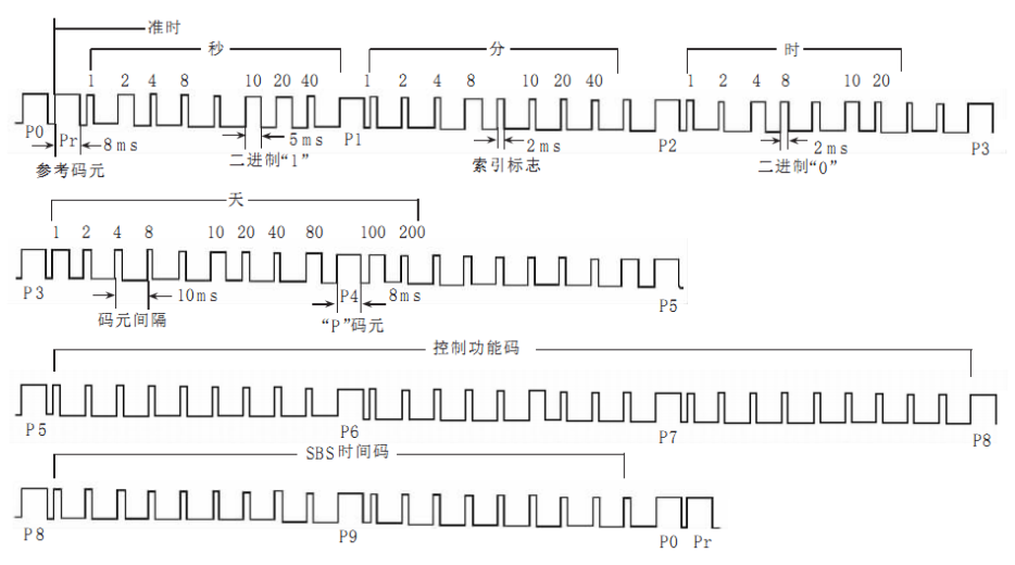
Figure 2
Applications of IRIG-B Time Synchronization
IRIG-B time synchronization is applicable in relay protection devices, power RTUs, power fault recorders, communication management units, and online power quality monitoring systems. Implementing an IRIG-B time synchronization solution based on the TI AM62x heterogeneous multi-core processor reduces development complexity for end users, shortens R&D cycles, and enables rapid product evaluation and technology prototyping.
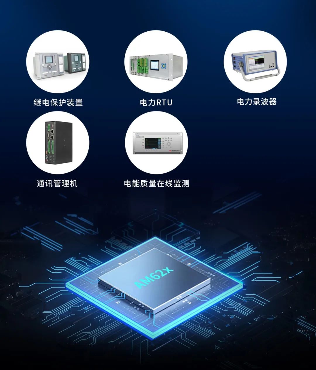
Figure 3
Common Implementation Approaches for IRIG-B Time Synchronization
IRIG-B time synchronization is typically implemented using either FPGA or MCU. The specific implementation methods are described below.
(1) Implementation Based on FPGA
To achieve precise synchronization between IRIG-B code and time signals (both input and output), a design architecture leveraging Field-Programmable Gate Arrays (FPGAs) has been proposed from an engineering perspective, following the encoding and decoding principles of IRIG-B used in modern test ranges. This approach involves handling multiple clock frequencies. FPGAs offer advantages in clock synchronization flexibility, high efficiency, low power consumption, and strong noise immunity. Results show that FPGAs can provide a common time reference for slave devices, keeping clock and signal delays under 200 ns, thus achieving highly accurate IRIG-B time synchronization.
However, developing IRIG-B functionality using FPGAs involves high complexity, long development time, and increased cost, which hinders fast time-to-market for products.
(2) Implementation Based on MCU
A Micro Control Unit (MCU) can be used to parse the IRIG-B timing sequence and extract time information, which is then synchronized to other processing cores.
MCU-based IRIG-B solutions feature simple architecture, lower development costs, and high synchronization accuracy, meeting requirements across various industrial applications.
AM62x IRIG-B Time Synchronization Solution
This section describes an IRIG-B signal decoding implementation using the MCU core (Cortex-M4F) of the TI AM62x processor.
The AM62x integrates both Cortex-A53 and Cortex-M4F cores. The IRIG-B time synchronization function can be implemented on the Cortex-M4F core, eliminating the need for additional external MCU hardware. This internal MCU-based approach simplifies hardware design and accelerates product development.
(1) Case Description
A satellite clock synchronization device acquires standard time via a GPS antenna module and outputs an IRIG-B code signal. This signal is converted into a logic-level signal by the RS485 transceiver on the evaluation board and sent to the Cortex-M4F core. The Cortex-M4F core reads the GPIO pin level, decodes the IRIG-B timing, extracts the time data, and then sends it to the Cortex-A53 core via TI-RPMsg for time display. The system block diagram is shown below.
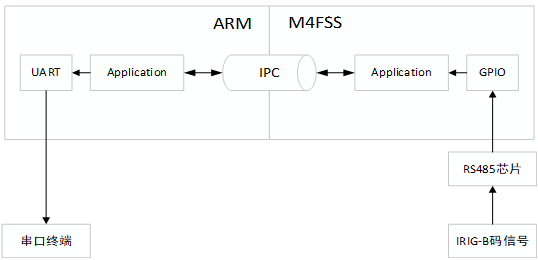
Figure 4
(2) Test Procedure
Testing must be conducted in an open-sky environment. Ensure the RUN indicator on the satellite clock synchronization device is steadily lit (indicating normal operation); otherwise, check the GPS antenna connection.
Since the RS485_2 UART5 interface on the baseboard is a peripheral of the Cortex-A53 core, a jumper wire must connect pin 3 of the RS485 chip (U30) to pin 4 of the EXPROT connector (J11)—which corresponds to a GPIO pin on the Cortex-M4F core. The IRIG-B signal output from the satellite clock device passes through the RS485_2 UART5 interface on the baseboard and then enters the Cortex-M4F core via pin 4 of J11.
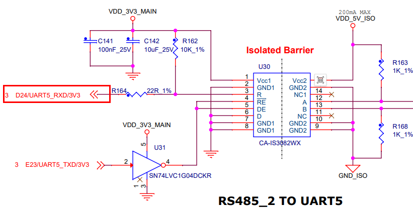
Figure 5
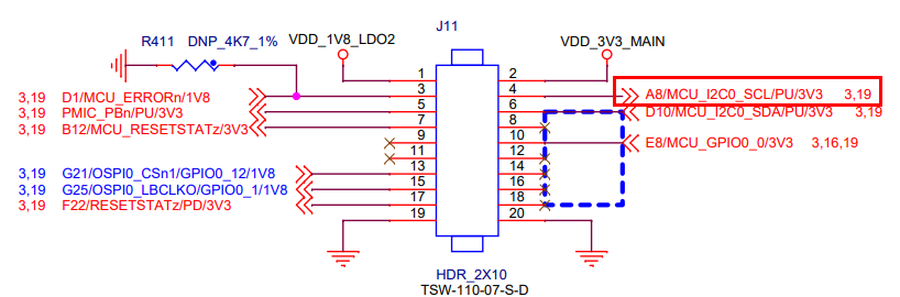
Figure 6
Connect the ANT port of the satellite clock synchronization device to the GPS antenna module. Connect the "+" terminal of the device's OUT1 port to the "A2" terminal of the RS485_2 UART5 interface on the evaluation board, and the "-" terminal to the "B2" terminal. The hardware connections are illustrated below.
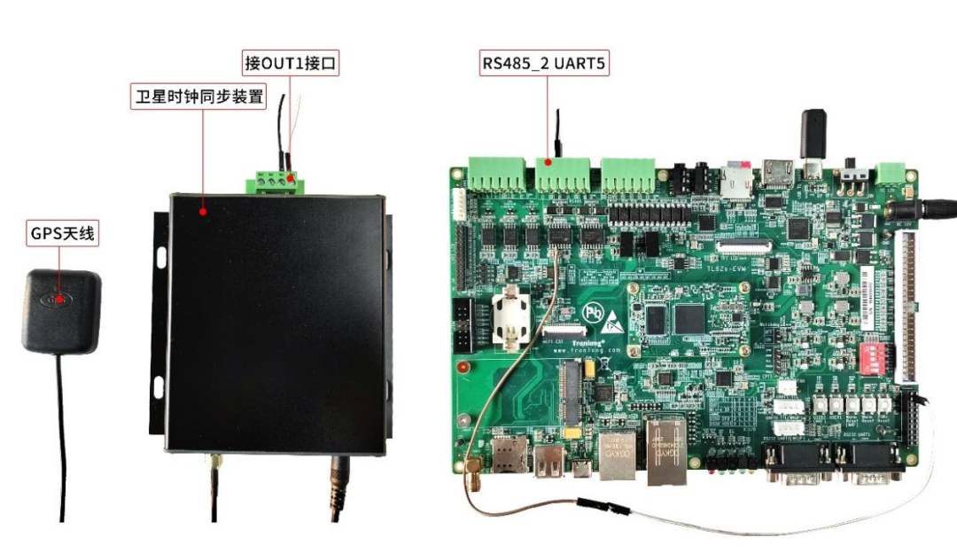
Figure 7
Copy the device tree file tl62x-evm.dtb from the case directory dts\bin\ to the /boot/ directory on the Linux system boot card, replacing the existing tl62x-evm.dtb file. Then copy the am62-mcu-m4f0_0-fw firmware file and the irig_b_decode executable from the case bin directory to the /home/root/ directory in the Linux system's file system.
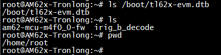
Figure 8
Power on the evaluation board and boot from the Linux system card. Execute the following commands sequentially to update the Cortex-M4F core firmware and reboot the board.
Target# rm /lib/firmware/am62-mcu-m4f0_0-fw
Target# cd /lib/firmware/
Target# ln -sf /home/root/am62-mcu-m4f0_0-fw am62-mcu-m4f0_0-fw
Target# sync
Target# reboot

Figure 9
Run the following command to check the mapping between the Cortex-M4F core and remoteproc:
Note: The RemoteProc name corresponding to the Cortex-M4F core is
5000000.m4fss.
Target# head /sys/class/remoteproc/remoteproc*/name
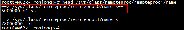
Figure 10
Based on the query result, run the following command to view the Cortex-M4F core program log and confirm its operational status:
Target# cat /sys/kernel/debug/remoteproc/remoteproc0/trace0

Figure 11
Execute the following command to view program runtime parameters:
Target# ./irig_b_decode -h
Note:
rproc_id: Core ID. The Cortex-M4F core ID is 9, with default ID 0.
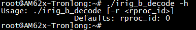
Figure 12
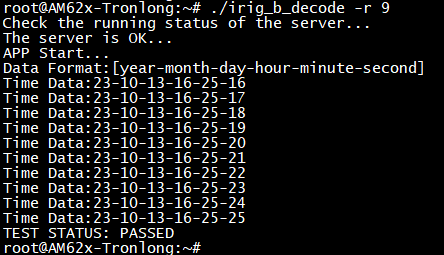
Run the following command to decode the IRIG-B timing and extract time information. The serial terminal will display the current date as shown below.
Target# ./irig_b_decode -r 9