Domestic Phytium ARM+FPGA Power Industry DCS Joint Solution
Overview of the Joint Solution
In the development of thermal power generation, as societal demand for electrical resources continues to rise, the previous coarse power generation methods are no longer viable. More refined generation is required to maximize resource utilization. Such control must be achieved through automation technology, as manual operations alone cannot meet these requirements. As a critical component of national infrastructure, the power system can enhance generation efficiency and safety by adopting domestically produced control systems. Developing an innovative, domestically sourced distributed control system (DCS) based on Phytium CPUs reduces reliance on foreign CPUs, enhances the level of indigenous innovation in core control equipment, mitigates technological risks arising from international fluctuations, and promotes the healthy development of the ecosystem surrounding domestic CPU technologies and products.
The DCS based on Phytium CPUs applied in this project has been redesigned by incorporating the advantages of the existing maxDNA system used in thermal power plants. Its core components include a highly reliable, embedded hardened operating system and distributed control units powered by the domestic Phytium CPU. The primary application of this project is a new generation of DCS based on independently developed domestic processors, encompassing an I/O layer based on rail-mounted installation and advanced measurement technologies, a process automation control layer, and a monitoring system layer. Additionally, an integrated information security architecture for the DCS is proposed, incorporating control command encryption and authorization, SBP access digital signatures, malware and network intrusion protection, network auditing, host hardening, and automatic configuration backup and recovery.
Solution Details
The process control station DPU module designed in this project operates under a networked real-time multitasking operating system in a Linux environment. It serves as the computing and communication engine of the DCS, performing key functions such as I/O data acquisition, data processing, control computation, and control command output.
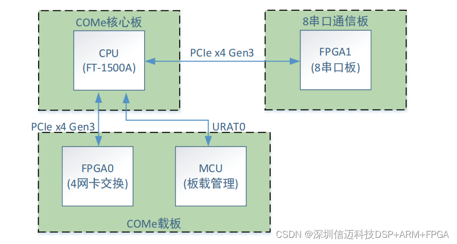
The DPU consists of two printed circuit boards. It uses the Phytium FT-1500A as the central processing unit (CPU) responsible for task-level processing; an FPGA as the network processor handling network data processing; an MCU as a coprocessor managing low-level I/O and basic event logging; and a COMe module acting as a multi-serial gateway dedicated to scanning I/O, providing high-speed multi-serial event services. Overall, each of these four chips runs independent software functions while also involving inter-chip logical state judgment and processing. The overall interconnection diagram of these four chips is shown below:
1. Hardware Requirements
Hardware Block Diagram and Functional Unit Descriptions
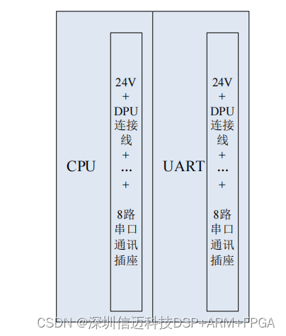
A complete DPU consists of two separate modules with independent housings—left and right—referred to as the CPU module and UART module, respectively. The socket definitions at the bottom of the modules are identical, allowing the left and right positions to be interchangeable during installation.
The overall hardware layout of the DPU is shown in the figure below:
In a DCS system, two DPU modules are installed on a single backplane to form a redundant DPU pair.
CPU Module (Board A): Uses a Phytium CPU module + carrier board design (with built-in 24V to 12V power conversion);
UART Module (Board B): Uses an FPGA + serial communication design (with built-in 24V to 5V power conversion, powering only the board itself);
Backplane: Uses PCIe x4 connection with CPCI connectors; eight serial ports are connected via pre-wired DB25 cables to configured modules.
The overall functionality of the DPU is illustrated in the following diagram:
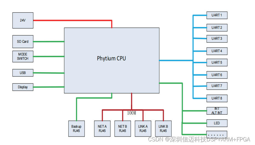
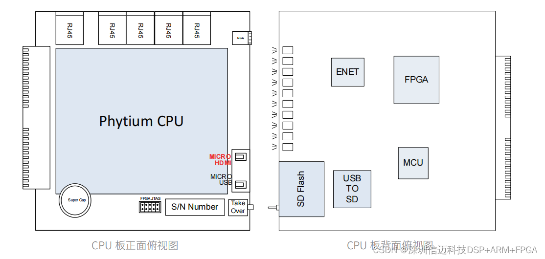
2. CPU Module (Board A) Hardware Structure and Interface Requirements
Considering enclosure universality, the DPU hardware dimensions must match the module size: PCB size of 125mm × 125mm, thickness of 1.6mm, and standard interfaces including an SD card slot, Micro USB, VGA, 100Mbps Ethernet, and Gigabit Ethernet. Debugging interfaces must include three USB ports and one VGA port, connecting to keyboard, mouse, debug port, and display, respectively. A rotary switch is used for mode selection, supporting 16 modes (0–F), connected to the MCU on Board A. The SD card interface module is implemented via a USB interface chip (USB2244), supporting SD cards up to 2GB. Four 100Mbps Ethernet expansion modules implement MAC functionality via the PCIe bus and an FPGA chip (Altera), interfacing with the KSZ8995MA chip (PHY function). Common-mode, differential-mode, and electrostatic discharge (ESD) performance must be considered.
The redundant Gigabit Ethernet interface directly uses the onboard Gigabit Ethernet expansion of the Phytium module, with consideration for differential-mode, common-mode, and ESD performance.
A supercapacitor (1.5F/5.5V) is connected in parallel to maintain the 3.3V power for the real-time clock during power loss. The inter-board interface uses a 10/100Mbps Ethernet interface extended from the Phytium module, connecting the CPU board and communication board. Performance and signal integrity testing must be considered during design, with communication tested under 2000V coupling.
Temperature measurement includes both carrier board and CPU temperature. The ADP75CIM temperature sensor on the carrier board is connected to the MCU on Board A. CPU temperature is read internally by the DPU from the motherboard's built-in temperature sensor.
Power-loss data storage is managed by the MCU on Board A, which controls the AT93C46D (EEPROM, 1K) chip used to store manufacturing date and version information.
The power input is 24V DC, converted on-board to 12V for internal use only.
The MCU has a separate power supply and connects to an SPI Flash (M-class), communicating with the Phytium processor via UART0. It provides power-on self-test at startup, PCB version identification (four bits, adjusted via resistor pull-up/down), CPU watchdog feeding, LED control, button input, and overall board fault monitoring.
3. Electromagnetic Compatibility and Protection Design
In accordance with DL/T 1083-2008 "Technical Conditions for Distributed Control Systems in Thermal Power Plants," the DCS hardware must meet the following electromagnetic compatibility (EMC) requirements:
- Electrostatic Discharge Immunity: Complies with GB/T 17626.2. Industrial Level 3: ±6kV contact discharge, ±8kV air discharge.
- Electrical Fast Transient/Burst Immunity: Complies with GB/T 17626.4. Industrial Level 3: ±2kV peak on power lines, ±1kV peak on I/O lines.
- Surge (Impulse) Immunity: Complies with GB/T 17626.5. Level 3 test: ±2kV peak.
- Voltage Dips, Short Interruptions, and Voltage Variations Immunity: Complies with GB/T 17626.11. Voltage dip and short interruption tests: 100% for 0.5 and 1 cycle; 60% for 0.5 and 5 cycles; 30% for 5 and 50 cycles. Voltage variation: 40% test level, rise/fall time of 2s ±20%, sustained low voltage for 1s ±20%.
- Radiated Radio Frequency Electromagnetic Field Immunity: Complies with GB/T 17626.3. Frequency range: 80MHz–1000MHz, with equipment installed in standard DCS cabinets. Level 2: 3V/m test field strength; Level 3: 10V/m test field strength.
4. Mechanical Design
Hardware PCB dimensions: 125mm × 125mm.
The CPU module is located on side A of the DPU board to facilitate heatsink installation. The design ensures convenient SD card insertion/removal, accessible USB and display ports, and places all Ethernet interfaces at the top. The enclosure design includes an RJ45 connector guide rail to prevent installation issues.
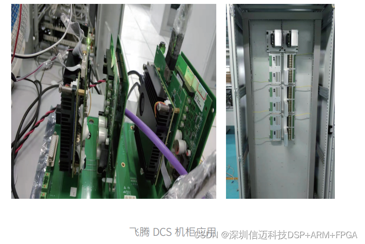
Implementation Results
Industrial control network information security is gaining increasing attention, with numerous national and industry regulations and standards already issued. As a critical component of industrial control systems, large-scale distributed control systems often manage infrastructure vital to national economy and people's livelihood. Strengthening their network information security is therefore especially important in the current environment.
This project implements a comprehensive DCS information security architecture based on the domestic Phytium chip platform. By integrating technologies such as encrypted control commands and authorization, SBP access digital signatures, malware and network intrusion protection, network auditing, host hardening, and automatic configuration backup and recovery, it effectively constructs a robust industrial control system network security framework while minimizing adverse impacts on the DCS's operational functionality, efficiency, and reliability.
Given the extremely high requirements for real-time performance, reliability, and computational capability in power plant DCS, both the operating system and application software must meet stringent standards beyond just hardware capability and stability.
The Phytium processor has been enhanced for real-time performance in industrial control applications. It uses a special memory to store real-time tasks, eliminating the need for DDR scheduling and enabling consistent access times. The on-chip network has been optimized for real-time operations, supporting fast scheduling of real-time tasks. Interrupt service routines are also stored in this dedicated memory, improving interrupt handling speed, and memory access interfaces have been optimized for real-time performance.
The Phytium processor supports two operating modes: secure and non-secure, which are completely isolated with independent resources. These modes are separated at both the processor execution level and memory level, dividing memory into secure and non-secure regions. Ordinary tasks, including the operating system, can only access non-secure memory, while secure-mode tasks can access all memory. This allows high-security control applications, such as those requiring secure host communication, to run in secure mode, while less security-sensitive applications like data communication and human-machine interaction run in non-secure mode, thereby preventing human errors from compromising high-security tasks.
The process control station can distribute task processes across different CPU cores to achieve enhanced security.
Key Technologies and Innovations of the Project:
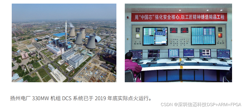
- Secure process control station based on domestic Phytium CPU, designed for 330MW thermal power units.
- Multi-core CPU process optimization and scheduling technology.
- Embedded high-real-time hardened operating system customized for the domestic Phytium CPU based on open-source Linux.
- Graphical multi-boot redirection UEFI boot technology tailored for the Phytium CPU architecture.
- Integrated DCS information security architecture incorporating control command encryption and authorization, SBP access digital signatures, malware and network intrusion protection, network auditing, host hardening, and automatic configuration backup and recovery.
Partner Products
- Thermal Power Plant DCS Systems
- Transformer Protection Systems for Thermal Power Plant Generating Units
Successful Cases