Essential Guide to Powering NI Automated Test Systems: Demystifying Power Planning
Just as you need to plug in a computer before use, selecting the right power supply is a primary concern for automated test systems—albeit a more complex one.
For example, geographical location must be considered, as public power grids in different countries or regions deliver varying line power levels. Practical experience in power layout and equipment selection includes adding approximately 20% headroom when powering the system to accommodate peak power usage and future expansion of the test system.
As outlined in Power Planning for Automated Test Systems, other critical factors include electromagnetic interference (EMI) or line filtering, power budgeting, power distribution units (PDUs), and power status monitoring.
ps: Download the white paper at the end of this article.
Connecting Power to the System
The best practice for powering an ATE system is to use a power inlet panel or line input panel. This isolates internal power wiring from the point where main voltage is applied. A power inlet panel allows the test system to be equipped with appropriate power connectors—those rated for the voltage and current required by the system.
NI power inlet panels support multiple connector types and power ratings, meeting diverse power requirements and geographic needs. Figure 1 shows examples of power panel connectors. High-quality power panels should also include circuit protection (such as circuit breakers and fuses) to safeguard the system from power surges or incorrect power source selection. Advanced models may additionally integrate electromagnetic interference (EMI) filters, surge suppressors, and other connectivity features for signal transmission into the system.
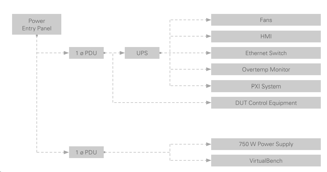
Figure 1. Power layout includes all devices within the test system and illustrates the power flow from the source through the test system to end-use equipment.
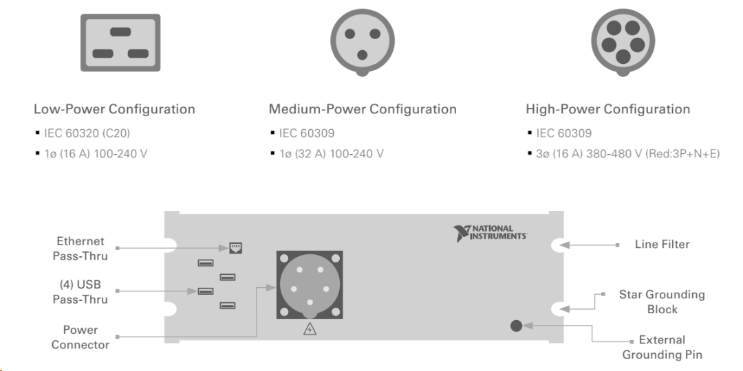
Figure 2. Power inlet panels provide the necessary connectivity to bring power into the system. These panels can use various standard power connector types, and high-quality models offer additional features such as filtering or emergency stop relay functions.
Geographical Factors – Line Power Varies by Region
When selecting a power panel for a test system, the geographical location of the tester or test equipment is a key consideration. Additionally, when planning a new test system, power standards and grid infrastructure, safety requirements, and deployment complexity—all influenced by geography—must be taken into account.
Grid Standards
Public power grids in different countries or regions deliver different line power levels. Each country or region has established standards for RMS voltage, AC frequency, connectors, and current ranges within its grid.
Public power grids typically use the following power configurations:
-
Single-phase power consists of one live (hot) wire and one neutral wire for conducting alternating current. Voltages typically range from 100 V to 240 V. For example, Japan uses 100 V, while many other countries operate between 220 V and 240 V. In the United States and Canada, the supply voltage ranges from 110 V to 120 V.
-
Split-phase power, also known as two-phase power, consists of two live wires and one neutral wire, with the two live wires providing voltage at equal positive and negative offsets. In the U.S., split-phase systems are typically 120 V, with a 180-degree phase difference between the two live wires. Since the wires carry 120 V and -120 V respectively, each can be paired with the neutral to create two separate 120 V single-phase circuits, or used together to form a 240 V single-phase circuit.
-
Three-phase power consists of three live wires and one neutral wire, with each live wire phase shifted by 120 degrees from the others. Most buildings in the U.S. use 208Y/120 V power, delivering 120 V across three live wires with a constant 208 V output. Many industrial facilities use 480Y/277 V systems, providing the 480 V needed for large machinery.
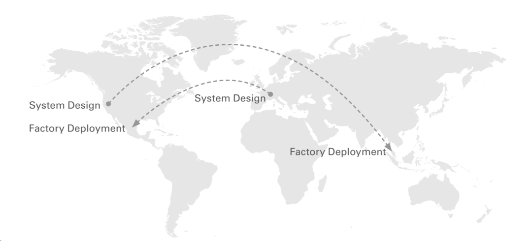
Figure 3. Deploying test systems across multiple countries or regions requires flexible system design. When developing such systems, it is essential to consider local power standards and certifications in advance.
Global Deployment
Test systems are often designed in one location and deployed in another—sometimes across multiple geographies. Deploying a single system in multiple locations introduces a new set of requirements. Deploying a system in Malaysia is fundamentally different from deploying it in the R&D facility or even the building where it was developed.
For example, an automotive engine control unit (ECU) test system may be developed at an R&D center in Detroit but deployed in a factory in Mexico. During system design, the grid standards and power quality in Mexico must be considered, and the system must be verified to meet all required safety and regulatory certifications before shipment. When designing test systems for global deployment, the following factors should be considered:
- Grid voltage standards and configurations
- Grid quality and reliability
- Material compliance (e.g., RoHS)
- Energy compliance (e.g., CE, PSE, or KC certifications)
- Trade compliance and import/export regulations
Electromagnetic Interference – Considering EMI and Line Filters
High-energy signals carried by the power grid often emit electromagnetic noise. Most noise on power lines is relatively consistent and can be planned for in advance. However, no power grid is perfect, and non-standard noise may exist in the power signal. Such noise can affect measurements made by instruments in the system and may even cause the system to fail compliance certifications.
To protect test systems from unexpected noise sources on power lines, the most common solution is to use EMI and line filters. Line filters are designed to operate within specific voltage and current ranges and filter signals within a defined frequency band. For example, a line filter may have a maximum rating of 250 V and 10 A, with an operating frequency range from 150 kHz to 1 MHz. Ensure that the selected line filter matches the test system’s power requirements and effectively suppresses unwanted noise frequencies. NI power inlet panels include EMI/line filters to protect sensitive measurement equipment.
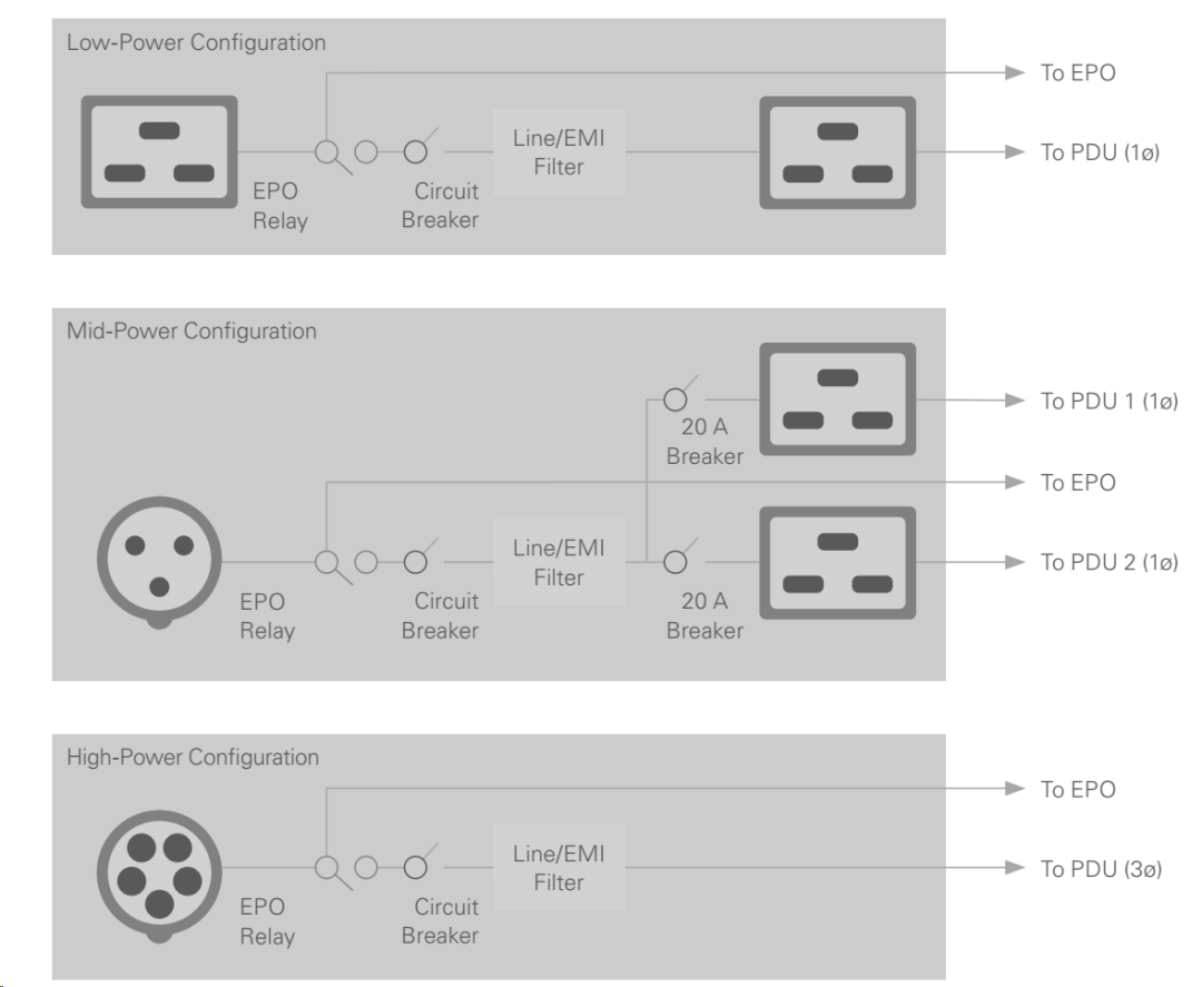
Figure 4. Circuit breakers and line/EMI filters are critical for protecting equipment in the test system and ensuring proper instrument operation and measurement accuracy. Examples of low-, medium-, and high-power configurations of a power inlet panel are shown.
Power Budgeting – Optimizing Power Distribution
Power budgeting is a critical step in planning test system resources and components. Every device must receive the correct amount of current at the proper voltage. Power budgeting must be performed for the entire system and at each power distribution point within it. After calculating the required power levels, standard rules can be applied to these values to optimize power distribution across the test system.
System Power Budget
To determine the system power budget, first identify the maximum power requirements of all devices in the test system. The total should include expected specifications for all components—voltage, current, and wattage. In many cases, current is the most important metric in power budgeting. Since a given transmission line can only carry a limited amount of current, current must often be carefully distributed across the system using a power distribution unit (PDU).
Power consumption for a given device is typically specified in the user manual and may include multiple values under different operating conditions. In some cases, both typical and maximum (worst-case) power consumption are specified. It is advisable to start with the maximum power requirement as a conservative safety margin, then reduce it by a given percentage (typically 30% to 40%) to arrive at a more realistic power estimate. Figure 5 shows the maximum power requirements when standalone instruments are integrated into a test system.
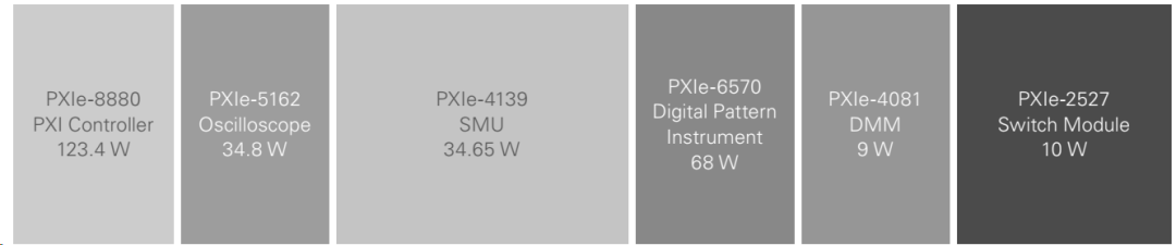
Figure 5. The total power consumption of a PXI chassis is the sum of the power consumed by all modules within it. As shown above, a fully loaded instrument chassis consumes 526.9 W under worst-case conditions.
Additionally, the guide provides detailed explanations of the following sections:
☑ Power Distribution Units (PDUs): A properly selected PDU ensures that all system components receive adequate power, balances power loads across components, and prevents overcurrent conditions.
☑ Power Status Monitoring: Power status refers to parameters such as voltage and current. In automated test systems, power status must be monitored and managed in real time to ensure normal operation of all components.
☑ Grounding: Grounding is a critical measure for ensuring power system safety. By connecting the power system’s ground wire to earth, the system can be protected from damage due to lightning strikes or other electrical faults.
☑ Best Practices for Component Procurement: When purchasing components for an automated test system, various factors must be considered, including performance, reliability, and cost. Components should be selected and configured according to actual system requirements to achieve optimal performance and results.