RK3568+Codesys+Xenomai Real-time SoftPLC Motion Control Solution
CODESYS Software Architecture
CODESYS software is divided into a three-layer architecture, as shown in the diagram below:
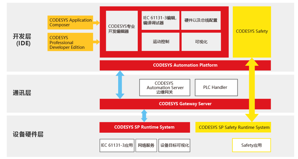
1. Development Layer
The CODESYS Development System (with comprehensive online and offline programming capabilities), compilers and their accessory components, visualization interface programming components, etc., are provided. Additionally, optional motion control modules are available to users, making its functions more complete and powerful.
IEC 61131-3 Editor. CODESYS provides all five programming languages defined by IEC 61131-3: such as Structured Text (ST), Sequential Function Chart (SFC), Function Block Diagram (FBD), Ladder Diagram (LD), and Instruction List (IL). Furthermore, it also supports the Continuous Function Chart (CFC) programming language.
Compiler: Responsible for converting applications in CODESYS into machine code and optimizing the performance of programmable controllers. When a user enters incorrect application code, they will immediately receive syntax error warnings and error messages from the compiler, allowing programmers to quickly make corresponding corrections. Users can develop projects using different hardware devices (systems) programmed with CODESYS without changing their programming method.
Hardware/Fieldbus Configurator: For hardware devices from different manufacturers and various fieldbus protocols, this component is responsible for setting the corresponding parameters within CODESYS.
Visualization Interface Programming: Visualization programming (Human-Machine Interface HMI) can be directly achieved within CODESYS, as the system has an integrated visualization editor.
Motion Control Module: Motion control functions have been integrated into CODESYS, forming the SoftMotion (CNC) software package. The PLCopen-based toolkit enables single-axis and multi-axis motion, electronic camming, electronic gearing, complex multi-axis CNC control, and more.
2. Communication Layer
Communication between the application development layer and the hardware device layer is realized by the Gateway Server in CODESYS, which has an OPC server installed.
CODESYS Gateway Server. It acts between the application development layer and the hardware device layer, enabling remote access using TCP/IP protocol or via buses like CAN. It is an integral part of the CODESYS Development Toolkit.
CODESYS OPC Server. For controllers programmed with CODESYS, regardless of the hardware CPU used, it has integrated and implemented multi-client functionality according to the OPC V2.0 specification, and can access multiple controllers simultaneously.
3. Device Layer
Before operating a hardware device using CODESYS, a programming development tool based on the IEC 61131-3 standard, hardware vendors must pre-install the CODESYS Runtime (real-time kernel) at the device layer. Additionally, functional extensions can be achieved by using CODESYS's optional components, such as the CODESYS Target Visualization programming module or the Web Visualization programming module.
4. Relationships between Layers in CODESYS Software Architecture
The CODESYS code execution mechanism is compiled execution. IEC programs written by users in the development layer are compiled into binary code by the integrated compiler, and then downloaded to the device layer via Ethernet or serial port. Ultimately, the application's files are converted into binary code and stored in the target device, where the corresponding program is executed cyclically according to the user-defined execution method.
Below is the architecture diagram of the CODESYS product series. Clicking on different parts of the image links to product introductions.
II. Specifications
Basic Parameters
SOC
Rockchip RK3568;
CPU
Quad-core 64-bit Cortex-A55 processor, 22nm advanced process, main frequency up to 2.0GHz;
GPU
ARM G52 2EE;
Supports OpenGL ES 1.1/2.0/3.2, OpenCL 2.0, Vulkan 1.1;
Embedded high-performance 2D acceleration hardware;
NPU
NPU, 0.8Tops@INT8 performance;
Supports one-click conversion of mainstream architecture models like Caffe/TensorFlow/TFLite/ONNX/PyTorch/Keras/Darknet;
VPU
Supports 4K 60fps H.265/H.264/VP9 video decoding;
Supports 1080P 100fps H.265/H.264 video encoding;
Supports 8M ISP;
Memory
1GB/ 2GB / 4GB/ 8GB LPDDR4X;
Storage
8GB/ 16GB/ 32GB / 64GB / 128GB eMMC;
TP Card Storage
Maximum support 64G;
Operating System
Android11.0/Linux;
Hardware Features
Network
Ethernet
Supports dual 10M/100M adaptive Ethernet;
WIFI/Bluetooth
2.4GHz Bluetooth: 4.2;
Optional: 5G dual-band;
Display Interfaces
3 display ports, supports eDP, LVDS, MIPI;
2 backlight driver ports;
Provides 3 display combinations;
Display Combination 1
Single/dual-channel LVDS 1080P@60fps;
4lane eDP 1080P@60fps;
Display Combination 2
4lane eDP 1080P@60fps;
4lane eDP 1080P@60fps;
Display Combination 3
4lane Mipi 1080P@60fps;
4lane eDP 1080P@60fps;
Touchscreen Interfaces
I2C
2 sets of I2C touchscreen control ports;
USB
External USB
1*Dual-layer Type-A, USB2.0 Host, Imax=1.5A;
1Dual-layer Type-A, including 1USB2.0 Host, Imax=1.5A and 1*USB3.0 OTG;
Internal USB
1*USB2.0 Host, Imax=2.0A;
1*USB3.0 OTG/Host, Imax=2.0A;
4*USB2.0 Host, Imax=0.5A;
Serial Ports
Internal Serial Ports
1*TTL serial port, Debug serial port, power supply voltage is 3.3V;
1*Configurable RS485/TTL serial port, power supply voltage 3.3V;
4*Configurable RS232/TTL serial ports, power supply voltage can be configured to 12V or 5V;
Audio Interfaces
Internal Speaker Interface
Speaker, left and right channels maximum support 8ohm/5W;
Internal MIC Interface
Microphone input;
Expansion Ports
Input/Output Expansion Ports
4*GPIO;
5*ADC;
Key Ports
RECOVERY_AD
Power on by pressing this key, USB OTG switches to firmware download mode;
Power Button + LED Indicators
Power button + Power indicator LED1 + Run indicator LED2;
Other Parameters
Power