Cost-effective All-domestic EMS Energy Storage Solution Based on RK3568 (Part 1) Overview
Energy Storage Industry Chain Framework
The energy storage industry chain can be divided into upstream "raw materials and production equipment," midstream "energy storage systems," and downstream "energy storage application scenarios and after-sales services."
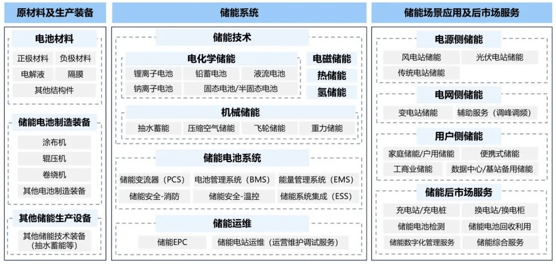
Figure 1 Energy Storage Industry Chain Framework Diagram
The "energy storage battery system" in the midstream of the industry chain mainly comprises four parts: "Energy Management System (EMS)," "Battery Management System (BMS)," "Energy Storage Converter (PCS)," and "battery pack." The battery pack feeds status information back to the Battery Management System (BMS). The BMS shares this information with the Energy Management System (EMS) and the Energy Storage Converter (PCS). The EMS then sends control information to the PCS and BMS based on optimization and scheduling decisions, controlling individual cells/battery packs to perform charging and discharging, etc.
(1) Energy Management System (EMS): Plays a decision-making role, primarily responsible for data acquisition, network monitoring, and energy dispatch.
(2) Battery Management System (BMS): Plays a sensing role, primarily responsible for battery monitoring, evaluation, protection, and balancing.
(3) Energy Storage Converter (PCS): Plays an execution role, its main function is to control the charging and discharging process of the energy storage battery pack and perform AC/DC conversion.
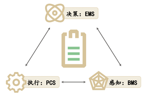
Figure 2 Logical Relationship Diagram of BMS, EMS, PCS, and Battery Pack
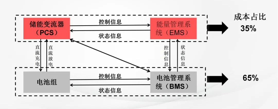
Figure 3 Schematic Diagram of Energy Storage Battery System
Xinmai Technology's "Six Major Energy Storage Solutions" are primarily applied to "energy storage battery systems."
Energy Storage EMS Solution
The Energy Management System (EMS) achieves energy control of the microgrid within the energy storage system through data acquisition, network monitoring, and energy dispatch, ensuring the normal operation of the microgrid and the entire system. Its main functions include monitoring and acquisition, data analysis and optimization, energy dispatch and control, and fault detection and safety protection. The functional requirements system block diagram is as follows:
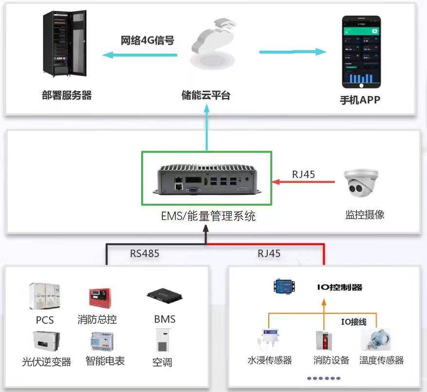
Figure 4
Energy Storage BMS Solution
The Battery Management System (BMS) primarily monitors the operating status of each battery within the battery energy storage unit, ensuring the safe operation of the energy storage unit, and together with the battery cells, forms the battery system. The BMS measures basic battery parameters, including voltage, current, and temperature, to prevent overcharging and over-discharging of the battery and extend battery life. The functional requirements system block diagram is as follows:
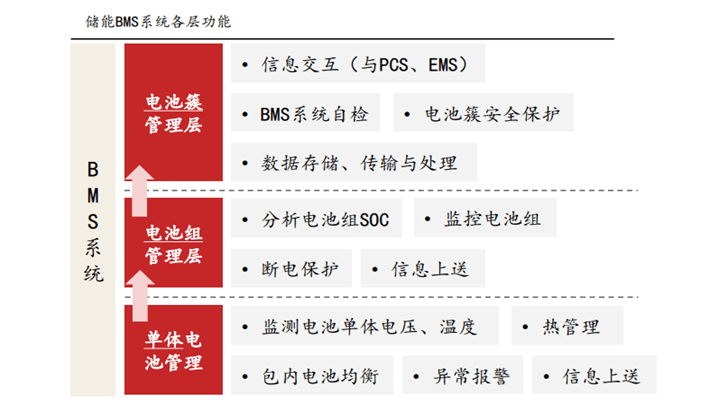
Figure 5
Energy Storage PCS Solution
The PCS energy storage converter is mainly composed of a DC/AC bidirectional converter, control unit, etc. By receiving backend control commands, it controls the converter to charge or discharge the battery according to power commands, achieving regulation of active and reactive power for the grid. At the same time, the PCS can obtain battery pack status information through communication with the BMS via CAN, RS485 interfaces, dry contact transmission, and other methods, enabling protective charging and discharging of the battery to ensure safe battery operation. The functional requirements system block diagram is as follows:
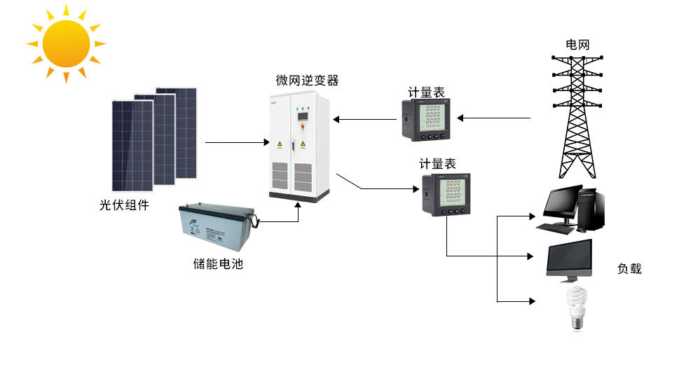
Figure 6