STM32 EtherCAT Bus-Type (1-to-4) Stepper Motor Solution
Chapter 1 Overview
Technical Features
Supports standard 100M/s bandwidth full-duplex EtherCAT bus network interface and CoE communication protocol with one input and one output (RJ45 interface), supports automatic mapping of multiple dynamic PDO groups and object dictionaries, supports automatic setting and saving of station ID, and supports SDO motor parameter setting and automatic saving.
Automatically adapts to commercially available EtherCAT bus master systems or PLC motion controllers, such as TwinCAT, Codesys, Omron, Trio, SOEM, IGH, Acontis, KPA, etc.
Supports standard CiA DS402 protocol, with built-in Cyclic Synchronous Position (CSP mode) and Homing control mode.
Supports driving up to 4 stepper motors, achieving multi-axis synchronous real-time control, offering the highest cost-performance ratio.
Built-in 12-channel 5V or 24V digital IO signal inputs, using bidirectional optocouplers, supporting NPN and PNP types, for general digital IO acquisition or left, center, right limit switches and homing reference functions (13-pin screwless quick-connect terminal KFM736L-5.0).
Built-in 8-channel digital signal outputs, for general digital IO output or brake and in-position functions, each channel can drive 500mA current (10-pin screwless quick-connect terminal KFM736L-5.0).
Quiet operation at low speeds, low vibration.
Stable operation at medium speeds, strong driving capability.
Smooth operation at high speeds, good dynamic response.
Vector FOC control technology, high current efficiency.
User-definable microstepping (default 256 microsteps, 51200 pulses/revolution).
User-definable holding current when the motor is enabled and running current during operation.
Phase loss protection, overcurrent protection, overvoltage protection, overtemperature protection, power supply reverse connection protection.
Chapter 2 Technical Parameters
EtherCAT_Step_Motor_V1.0, four-axis stepper motor driver, maximum single-axis drive current 3A. Can be used with 28/42/57 stepper motors.
The operating speed is best kept within 1200 rpm, because the torque of stepper motors decreases as speed increases. Driving 42/57 stepper motors below 300 rpm can achieve rated torque and absolute silence. Above 900 rpm, the motor is essentially in a no-load state. Pay attention to driver heat dissipation during use. The DC communication cycle of the EtherCAT bus can reach 125us, supporting homing mode and cyclic synchronous position mode.
Stepper motor acceleration/deceleration up to 500 rpm/s², maximum speed 3000 rpm, minimum speed 0.001 rpm.
Digital inputs support NPN and PNP triggering, digital output maximum current can reach 0.5A.
The recommended power supply voltage for the driver is 24V, and the DC power supply should have an output capability of 15A or more to ensure stable power supply to the driver.
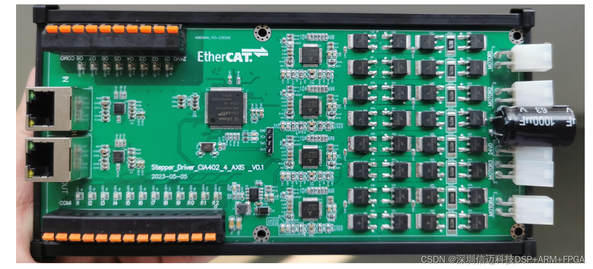
Product Dimensions: 90mm*200mm, the casing adopts a DIN35 standard rail.
Network Ports (Middle Left): RJ45 network port direct plug-in type. The upper one is the IN network port, and the lower one is the OUT network port. The bus operation status indicator is RUN1, and the error indicator is ERR1.
Digital Inputs (Upper Left): The COM port is the common terminal, and I1-I12 are digital input ports. The COM port can be grounded or connected to 24V. The digital inputs use bidirectional optocouplers, which can conduct in both directions. When a digital input channel is conducting, the corresponding green indicator light will illuminate.
I1-I3 are digital inputs for motor 1; when triggered, the corresponding input object dictionary of the bus displays 1, 2, 4.
I4-I6 are digital inputs for motor 2; when triggered, the corresponding input object dictionary of the bus displays 1, 2, 4.
I7-I9 are digital inputs for motor 3; when triggered, the corresponding input object dictionary of the bus displays 1, 2, 4.
I10-I12 are digital inputs for motor 4; when triggered, the corresponding input object dictionary of the bus displays 1, 2, 4.
Digital Outputs (Lower Left):
O1-O2 are digital outputs for motor 1; triggered when 1, 2, 4 are written to the corresponding output object dictionary of the bus.
O3-O4 are digital outputs for motor 2; triggered when 1, 2, 4 are written to the corresponding output object dictionary of the bus.
O5-O6 are digital outputs for motor 3; triggered when 1, 2, 4 are written to the corresponding output object dictionary of the bus.
O7-O8 are digital outputs for motor 4; triggered when 1, 2, 4 are written to the corresponding output object dictionary of the bus.
Stepper Motor Terminals (Right):
The 4-pin terminals are for stepper motors; from top to bottom, they are motor 1, motor 2, motor 3, motor 4.
24V Power Supply Terminals (Right)
Do not plug or unplug while powered, otherwise electric sparks will be generated. Do not place near other heat-generating equipment. Avoid dust, oil mist, corrosive gases, excessive humidity, and strong vibration environments. Flammable gases and conductive dust are prohibited. To ensure good heat dissipation, a sufficiently large installation clearance must be reserved during actual installation to maintain ventilation and heat dissipation. The DC driver power supply must not be reverse-connected. High-voltage drivers contain large-capacity electrolytic capacitors, which will retain high voltage even after power-off. Do not touch the driver and motor within 5 minutes after power-off.
Chapter 5 Software Operation
I. Placing the XML File:
First, locate the XML device description file provided by the vendor and copy it to the specified folder in the TwinCAT installation directory: C:\TwinCAT\3.1\Config\Io\EtherCAT Steper_Driver_Cia402_4_AXIS_V1.0.xml
Note: After copying, you must restart the TwinCAT software.
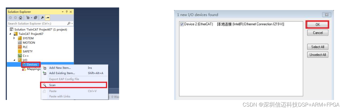
II. Starting TwinCAT: Create a new project in TwinCAT. Then click Scan to scan for devices.
After clicking sequentially as indicated by the red box, device information will appear, as shown in the figure below:
Motion Controller Application
- Integrated CODESYS IEC 61131-3 Programming Tool (programming tool), ST/LD/FBD/IL/CFC and other programming languages; CODESYS Runtime System (runtime system)
- Supports bus protocols, such as: CODESYS EtherCAT Master/CANopen/Modbus; CODESYS Visualization (visualization) HMI solutions, including Webvisu and secondary development kits;
- CODESYS SoftMotion (part1, part2 motion control) Basic (CAM); Supports single-axis relative motion, absolute motion, jog motion, driver homing motion, multi-axis interpolation, multi-axis point table motion, electronic gearing motion, and other functions. Applicable to vision positioning equipment, assembly equipment, dispensing equipment, labeling equipment, production lines, and other equipment.
Product Features
-
- Rich communication interfaces to meet control and communication needs in various scenarios
- Quad-core industrial-grade processor, high performance, low power consumption, high reliability
- Fanless design, compact casing
- Equipped with SylixOS, a large-scale real-time operating system with 100% independent kernel, supporting POSIX interface specifications; possesses completely independent and controllable intellectual property rights, meeting localization requirements, with high real-time performance, high reliability, and high security; provides a convenient and mature programming development kit, RealEvo-IDE
- Supports CODESYS for user secondary development
- Supports CODESYS EtherCAT/CANopen/Modbus and other protocol stacks
- Supports QT, providing a convenient graphical development environment
- Supports hard real-time functions, task switching in microseconds, interrupt response in nanoseconds