EtherCAT Bus-Type 4-Axis Motor Control Card Solution
Technical Features
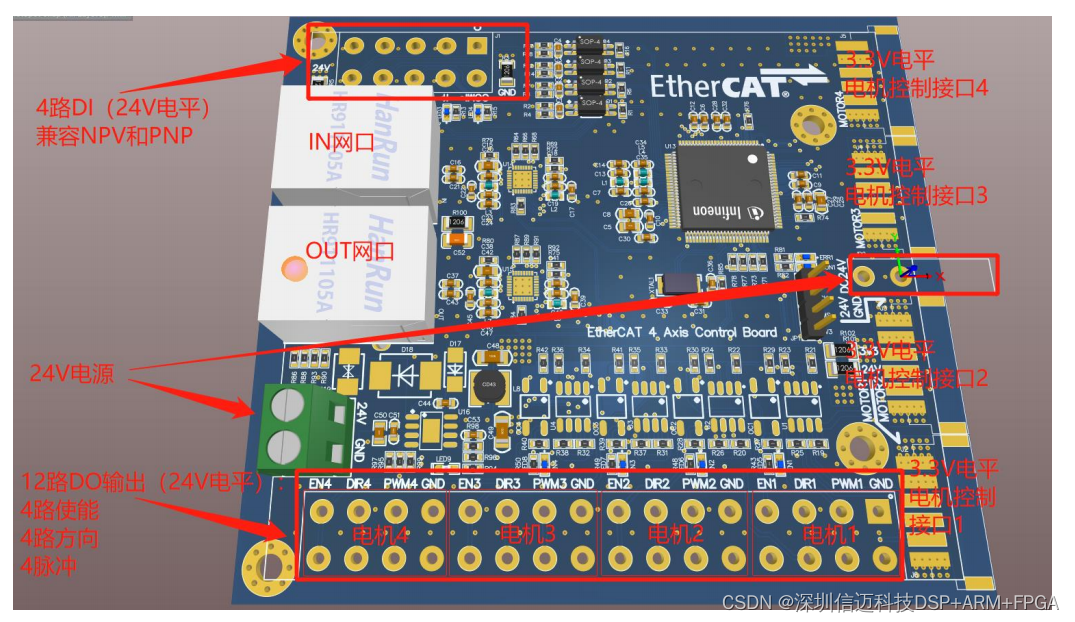
Supports standard 100M/s full-duplex EtherCAT bus network interface and CoE communication protocol with one input and one output (RJ45 interface), supports automatic mapping of multiple dynamic PDO groups and object dictionaries, supports automatic setting and saving of station ID, and supports motor parameter setting and automatic saving via SDO.
Automatically adapts to mainstream EtherCAT bus master systems or PLC motion controllers on the market, such as TwinCAT, Codesys, Omron, Trio, SOEM, IGH, Acontis, KPA, etc.
Supports standard CiA DS402 protocol, with built-in Cyclic Synchronous Position (CSP mode) and Homing control mode (Homing mode).
Supports control of up to 4 stepper or servo motors, achieving multi-axis synchronous real-time control, offering the highest cost-performance ratio.
Built-in 4-channel 24V digital I/O signal input, using bidirectional optocouplers, supporting NPN and PNP types, for general digital I/O acquisition or left, center, and right limit switches and homing reference functions (5-pin screwless quick-connect terminal KFM736L-5.0).
Built-in 12-channel digital signal output for controlling 4 motor drivers, each motor has three control signals: enable, direction, pulse; enables the EtherCAT bus to convert to pulse, direction, and enable signals for independent control of three motors, supports 3.3V and 24V level output (16-pin screwless quick-connect terminal KFM736L-5.0).
Phase loss protection, overcurrent protection, overvoltage protection, overtemperature protection, power supply reverse polarity protection.
Chapter 2 Technical Parameters
EtherCAT_Step_Motor_V1.0, a four-axis motor control board, outputs 4 enable signals, 4 direction signals, and 4 PWM signals, and can be used with stepper or servo motor drivers.
The DC communication cycle of the EtherCAT bus can reach 125us, supports Homing mode, Cyclic Synchronous Position mode, and the EtherCAT bus network port supports one input and one output.
The power supply voltage for the control board is 24V, the control board's digital outputs support 24V and 3.3V level output, the maximum digital output current can reach 0.5A. When the 4 motors are enabled, a blue indicator light illuminates.
Digital inputs 1-4 support NPN and PNP triggering, a green indicator light illuminates upon triggering.
Product Dimensions: 90mm*100mm, the casing adopts a DIN35 standard rail mounting.
Network Port (Middle Left): RJ45 network port,