Design of a Desktop CNC Lathe Control System Based on Dual STM32 and FPGA
Desktop CNC equipment offers significant advantages for small-sized part processing in terms of cost, power consumption, and footprint. There are roughly three implementation schemes for desktop CNC equipment: The first is a miniature machine tool paired with a traditional CNC system, but desktop CNC equipment is cost-sensitive. The second is a PC-based CNC system software and its corresponding interface card controlling a miniature machine tool [1]. Due to complex software settings, it's difficult to modify for different requirements, resulting in poor accuracy and low stability. The third scheme involves independently completing the CNC system design on a specific hardware platform.
Within scheme three, depending on the hardware platform, it can be divided into PC-based [2-3] and embedded chip-based [4-7]. PC-based CNC systems can simplify tasks like task scheduling and communication, enabling complex human-machine interaction functions such as simulation processing and trajectory display. However, introducing a PC not only increases size and cost, but also, because general-purpose operating systems do not meet the real-time requirements of CNC systems, it necessitates adding real-time kernel patches or using hardware to implement high real-time tasks in the CNC system [8-9]. Embedded chips highly integrate CPU, RAM, ROM, and rich peripherals on a single chip, offering significant advantages over PCs in terms of size, power consumption, and cost. STM32 is a series of 32-bit microprocessors developed based on the Cortex-M core, with clock frequencies ranging from 32 MHz to 480 MHz, which can balance the embedded CNC system's requirements for CPU real-time computing power and cost. Therefore, this design uses STM32 to complete the CNC system design, employs FPGA to assist STM32 in controlling specific actuators, and designs a desktop lathe [10] for verification.
1 CNC Lathe Control System Mode Classification
Traditional CNC system modes often have blurred boundaries, which can easily confuse beginners. An analysis of the functions and implementation methods of these modes can be summarized into two categories: manual processing and automatic processing.
A reasonable functional classification helps clarify task content and lowers the barrier to use. In specific implementations, there is an overlap in the implementation methods of the two modes, and some hardware and software can be shared. Based on the Client-Server (C/S) design pattern, the CNC lathe control system is divided into two parts: the client and the server. The client primarily handles human-machine interaction tasks, while the server mainly performs parameter modification, action execution, and the core functions of the CNC system, such as G-code execution. The two parts primarily communicate through a custom asymmetric communication protocol, where the server receives and executes client commands and returns execution results, cooperatively implementing the two processing modes.
2 Hardware Design
Hardware is the foundation of a CNC system. Hardware design must meet the CNC system's requirements for data processing capability, multi-axis linkage synchronization, storage capacity, and electromagnetic interference resistance. Due to space limitations, this section will not elaborate on specific circuit schematics, but will only analyze and design the hardware part of the CNC system from a requirements perspective.
2.1 Client Hardware Design
The main task of the client part is human-machine interaction, with screen display and virtual buttons being the primary HMI devices. To reduce workload and improve development efficiency, many embedded designs use serial screens for human-machine interaction [4, 11-12]. However, such designs are limited, and serial screens are typically for general industrial applications, not meeting high real-time requirements like coordinate display. Therefore, in the client hardware design, an STM32F429 + touchscreen is used for self-developed human-machine interaction. At the same time, fully leveraging the rich peripherals of STM32, USB and SD interfaces are added for external G-code input from USB drives, keyboards, and SD cards; Flash memory is used for on-board G-code storage; 32MB of SDRAM is added to expand the STM32F429's memory, also serving as display video memory; a handwheel interface is extended for connecting an external electronic handwheel; Ethernet and RS485 interfaces are reserved to increase system openness and functional expandability.
2.2 Server Hardware Design
Since the server undertakes most of the tasks in automatic processing, the server hardware needs to meet the real-time, synchronization, and stability requirements of the CNC system. An STM32F767, with a clock frequency up to 216 MHz and floating-point support, is used to meet the real-time requirements of the CNC system. An EP4CE15F484 is used to synchronously send motion commands for each axis to the motor drivers. SDRAM is added to expand memory, increasing the maximum number of G-code lines to prevent system crashes; FMC is used for master-slave communication between STM32 and FPGA; since the FPGA is directly connected to actuators and sensors, optocoupler isolation is added to prevent external signal interference.
2.3 Overall Hardware Design
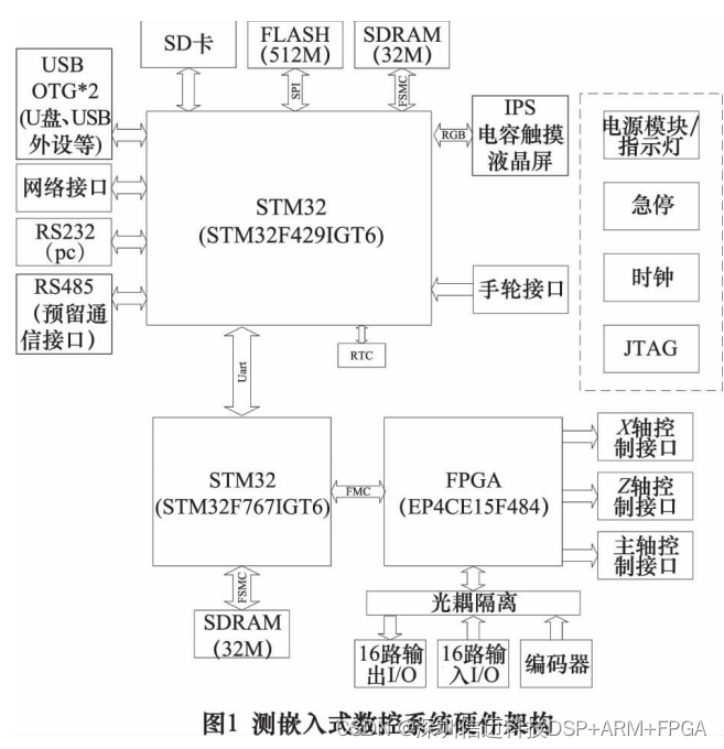
Although two MCUs are used to accomplish client and server tasks, considering size and installation, both parts are integrated onto a single PCB, sharing essential modules such as power supply, clock, emergency stop, and indicator lights. The overall hardware architecture of the CNC system is shown in Figure 1:
3 Software Design
Software design primarily involves analyzing and designing client functions and server tasks. Due to space limitations, and since many references [13-16] describe decoding, tool compensation, and interpolation, not all sub-function modules will be elaborated upon here.
3.1 Client Software Design
emWin is a graphical software library developed for embedded platforms. Using emWin widgets, interface editing can be done like building with blocks, and then the STM32's LTDC controller drives the display to show the interface. emWin supports touchscreens, periodically detecting touch interactions and obtaining click coordinates in the screen coordinate system. By comparing the click position with the interface widget position, it determines if the widget has been operated, and a response function is written in the widget's callback function to implement virtual button functionality. By encoding different button-class widgets, the corresponding code can be written to memory within the button widget's callback function to achieve virtual button input for standard G-code or other types of data. Traditional CNC lathes support the use of electronic handwheels. Compared to buttons, electronic handwheels allow for flexible micro-feeding, controlling motor feed speed based on rotation speed, providing great convenience for operations like tool setting.
FatFs is a file system module designed for embedded systems. FatFs performs data reading and writing based on sector information, provides necessary data protection, and offers generic operations for different storage media. 4Mbps serial communication is used between the client and server to meet the real-time requirements for large data command responses. The server returns various types of results. Serial reception interrupt parsing might cause significant timing jitter in the client system. Therefore, results, except those with high real-time display requirements (e.g., coordinates), need to be temporarily stored in a FIFO buffer, and parsed after other tasks are completed. Touch detection, screen display, and result parsing are macroscopically parallel tasks. Therefore, the embedded operating system μC/OS-III is used for task scheduling, and emWin and FatFs can also use resource protection mechanisms like semaphores provided by the operating system for shared resource protection.
3.2 Server Software Design
Due to the limited server memory size, modules such as decoding, tool compensation, and interpolation need to be executed in parallel to reduce buffer requirements, which introduces issues of task scheduling and shared resource management. With hardware advancements, MCU on-chip RAM size has increased, and external RAM can be added to expand system memory. Consequently, many parallel tasks can be converted to serial execution, thereby simplifying design, reducing system coupling, and increasing system robustness.
Since the server passively responds to client commands, when the server is idle, it should continuously check for commands delivered via data communication. Based on the command content, it should use function pointers to call service-type tasks such as parameter modification, action execution, and G-code execution. The parameter modification task not only provides necessary parameter changes for automatic processing, such as tool setting data, but also allows modification of motor parameters (max speed, acceleration, etc.) and machine tool parameters (max travel, front/rear tool posts, pitch, etc.), enhancing the flexibility of the CNC system. The sequence of action command transmission will inevitably disrupt the synchronization of linkage. Therefore, the action execution task only needs to consider single-axis movements at a given time, corresponding to the manual processing mode.
G-code tasks include sub-tasks such as decoding, tool compensation, speed planning, and G-code interpretation [16]. Text files read into the system via FatFs are stored as character arrays. If instructions are searched for during G-code interpretation, it cannot meet the real-time requirements for processing speed