[Domestic Virtual Instruments] Design of a Power Quality Analyzer Based on ARM+FPGA+8-channel High-speed AD to Replace National Instruments' Solution (Part 1) Introduction to the NI Solution
I. Background: Introduction to the Acquisition Solution Based on National Instruments
The data analysis system for the power quality analyzer designed in this paper uses National Instruments LabVIEW 2018 as its software development platform. Combined with the hardware platform, it achieves data acquisition, waveform display, and data analysis. The primary role of the hardware circuit is to attenuate and condition grid signals. It is responsible for converting grid signals into signals that can be input into a computer for analysis, making the hardware structure crucial for the entire design. 3.1 Signal Conditioning Circuit Design 3.1.1 Overall Structure of the Conditioning Circuit
Conditioning circuits typically include filtering, amplification, and isolation circuits. In practical power quality analysis systems, the signal amplitude output by Hall voltage and current sensors often does not match the range of data acquisition cards, and the signal-to-noise ratio is low, preventing direct input to the acquisition card. Therefore, this paper will design a conditioning circuit.
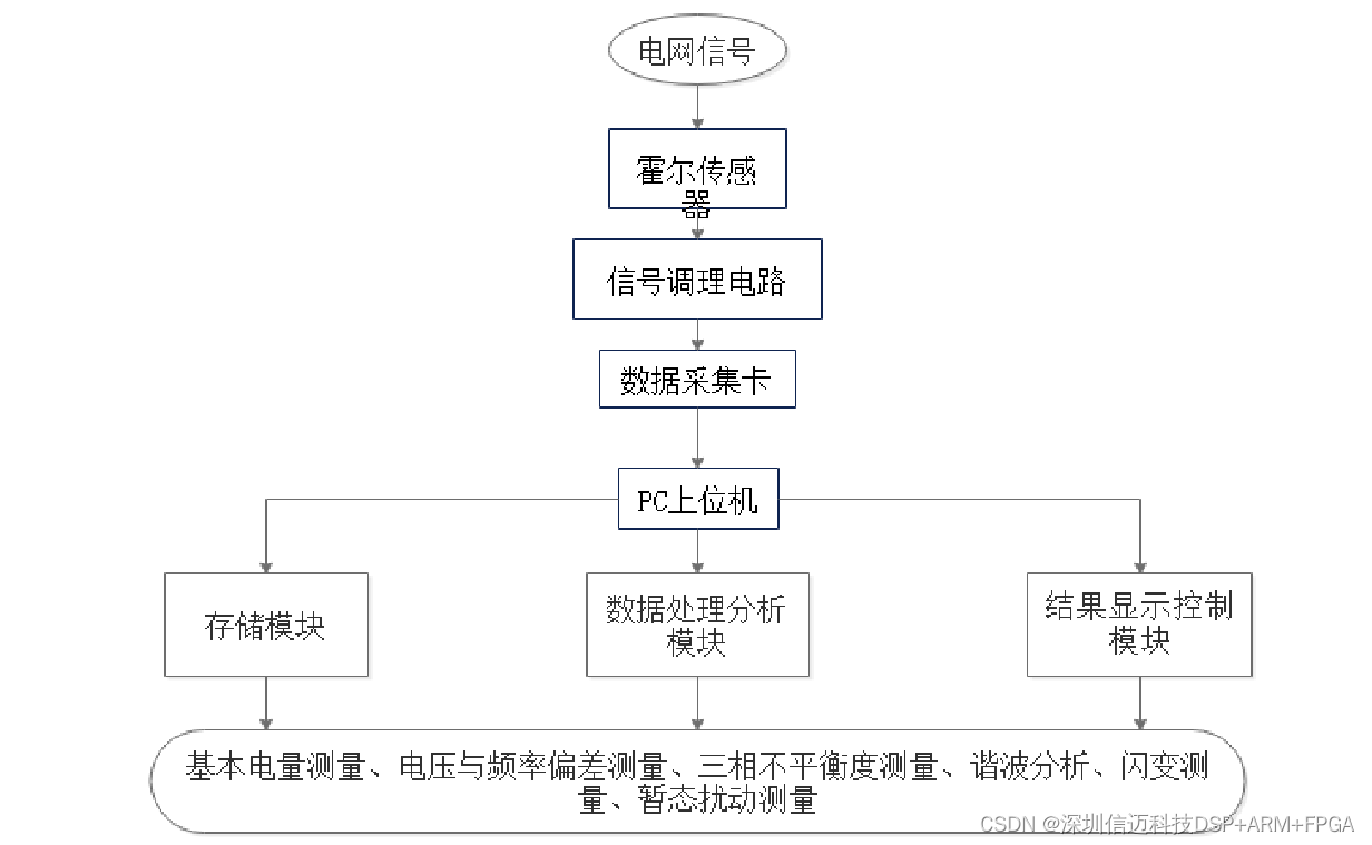
In this paper, the power quality analysis system will be divided into a data acquisition module, a data analysis module, and a results display and storage module. Other structures are shown in Figure 3-1. The process is as follows: (1) Signals from the power grid are transformed by sensors into voltage and current signals of a certain amplitude. These signals are then filtered by the conditioning circuit to ensure their amplitude meets the data acquisition card's range. Subsequently, the conditioned voltage and current undergo A/D conversion via the USB-6281 data acquisition card, and the discrete data is then transferred to a data buffer awaiting signal processing. (2) Algorithms in LabVIEW are used to calculate and analyze the data from the acquisition card. (3) The calculation results are displayed on the main interface of the analysis system, and the data is saved. The structure is shown in Figure 3-1 below.
3.1.2 Circuit Design
- Voltage and Current Sensors In power quality analysis systems, large voltage and current signals received from the power system cannot be directly connected to a data acquisition card because the typical range of DAQ cards is usually within a few volts. Therefore, before data acquisition, voltage and current must be transformed to fall within the DAQ card's range. Traditional electromagnetic and capacitive transformers have lower measurement accuracy and longer response times. Thus, this paper selects more advanced Hall-effect sensors for receiving voltage and current signals. Advantages of Hall sensors include: (1) Ability to monitor non-sinusoidal signals. (2) Good isolation performance between primary and secondary circuits, ensuring normal system operation. (3) Dynamic response time shorter than 7μs. (4) Good linearity, better than 0.1%. The Hall sensors used in this design operate in closed-loop compensation mode, which enhances data transmission efficiency and measurement accuracy. Hall sensors exhibit high linearity between their primary and secondary circuits. Specifically, the three-phase currents are converted into voltage signals by passing through a resistor on the secondary side of the current transformer, subsequently entering the signal conditioning circuit.
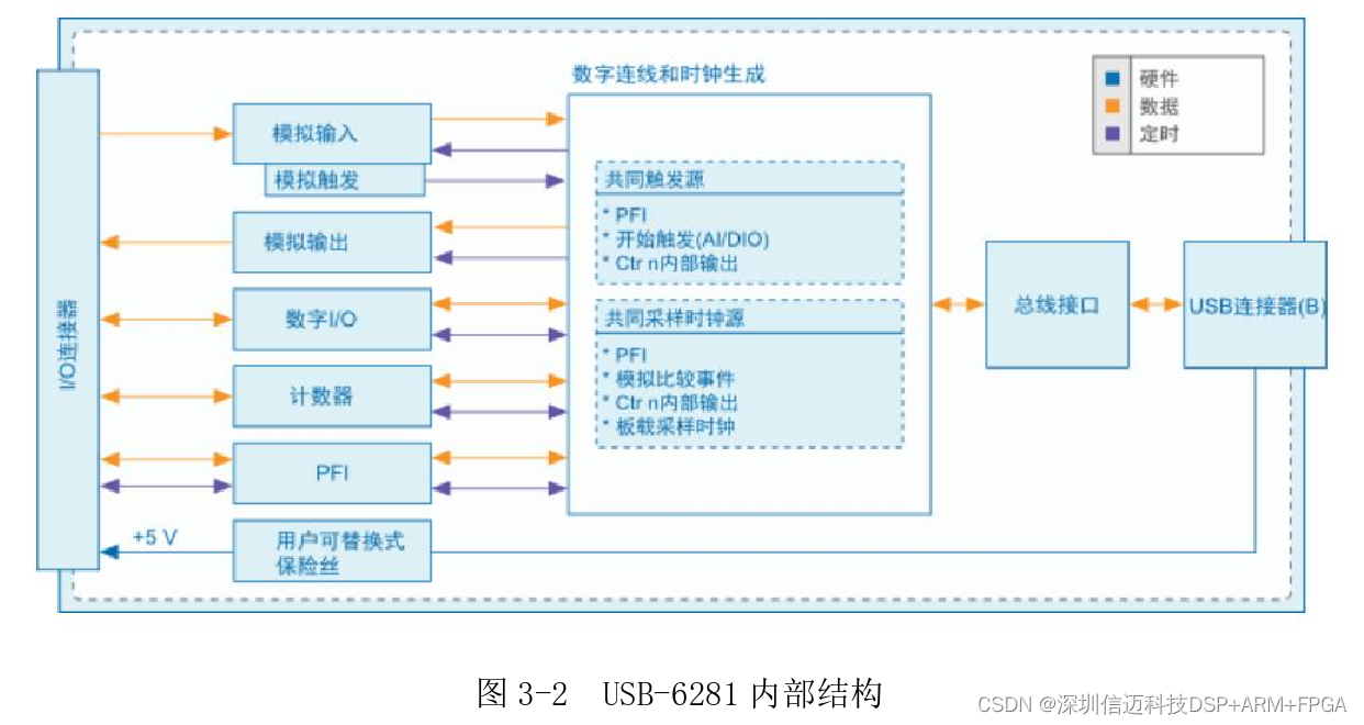
- Signal Conditioning Circuit The conditioning circuit is located between the sensors and the data acquisition card, comprising filtering, amplification, and isolation circuits. In practical power quality analysis systems, the signal amplitude output by Hall voltage and current sensors often does not match the range of data acquisition cards, and the signal-to-noise ratio is low, preventing direct input to the acquisition card. Therefore, a conditioning circuit needs to be designed to filter and amplify the power system signals. (1) Signal Amplification Circuit Since noise is prevalent in electronic circuits and sensors, interfering with signal transmission, voltage signals, even after filtering, may not meet the range requirements of the data acquisition card. Therefore, an amplification circuit is needed to transform the signal into a range that matches the DAQ card's input, thereby improving measurement accuracy. (2) Filtering Circuit As noise is widely present in electronic circuits and sensors, it needs to be suppressed. Simultaneously, to prevent signal aliasing, the device's sampling frequency needs to be increased; however, if the sampling frequency is too high, it can also reduce sampling accuracy. Before data acquisition, a low-pass filter is required to remove unwanted high-frequency signals. The frequency measurement range for National Class A instruments is 0-2500Hz [8], so high-frequency components exceeding 2500Hz must be filtered out. This design utilizes the NI USB-6281 data acquisition card, which includes low-pass filtering capabilities. 3.2 USB-6281 Data Acquisition Card NI's data acquisition cards are PC-based, offering a wide variety and strong adaptability. They support software development on multiple platforms. Figure 3-2 shows the block diagram of the USB-6281 data acquisition card.
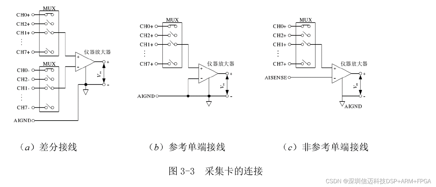
3.2.2 Data Acquisition Card Connection The NI USB-6281 acquisition card supports two signal wiring methods: differential wiring and single-ended wiring. As shown in Figure 3-3(a), with differential wiring, signals are directly connected to screw terminals without needing a fixed reference point. As shown in Figure 3-3(b), for referenced single-ended wiring, one end of the signal needs to be connected to a screw terminal and the other end to a ground terminal, also connected to the measurement system's ground. As shown in Figure 3-3(c), for non-referenced single-ended systems, one end of the signal is connected to a common reference terminal and the other end to a screw terminal, without connecting to the measurement system's ground. This paper chooses the differential method for measuring voltage and current signals to suppress common-mode signals present in them, thereby improving the accuracy of the measurement system.
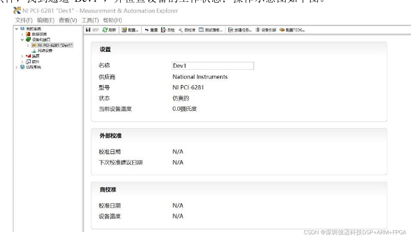
3.2.3 Management Software DAQmx DAQmx can be easily matched with hardware devices, and its main function is to perform self-tests on data acquisition cards. After the acquisition device has the DAQmx driver installed, the MAX management software can identify and configure it [58]. The operating steps for DAQmx software are: (1) Connect the data acquisition card to the computer; (2) Turn on the power; (3) Open the MAX software, locate channel "Dev1", and check the device's operating status; the operational diagram is shown below.
3.3 Virtual Instrument Technology
3.3.1 Virtual Instruments
Currently, a significant development direction for instruments and meters is their integration with PCs. Since the advent of virtual instruments, National Instruments' LabVIEW graphical development tool has become the preferred choice for programmers. The core idea of LabVIEW is "software is the instrument," i.e., virtual instruments. It has introduced visual programming and intuitive, concise user interfaces to virtual instrumentation.
3.3.2 Introduction to LabVIEW
LabVIEW is a graphical programming language that creates applications using graphical blocks. Previously, people were accustomed to using text-based programming to implement algorithmic functions. Now, the same functionalities can be achieved using "functions" and "controls" within the LabVIEW language. This programming approach is simple, efficient, and easy to understand, significantly reducing the difficulty of program design, making it the most widely used software in the field of virtual instruments today.
Compared to traditional instruments, virtual instruments have the following characteristics: (1) The system's control panel is virtual, not physical. (2) The instrument's measurement functions are implemented through algorithmic programming rather than hardware circuits.
LabVIEW also has the following features: (1) Cross-platform compatibility. LabVIEW supports Windows, Mac OS X, Linux, and other operating systems to meet the needs of various programmers. (2) Open development platform. LabVIEW provides an open development platform, offering diverse software support. (3) Diverse data display methods. LabVIEW provides users with various display controls such as tables, dials, and charts, as well as multiple display methods like digital display, analog display, polar plot display, and spectrum display. (4) Powerful testing capabilities. LabVIEW has the largest library of device drivers and supports data sharing through various interactive communication methods such as DDE and SQL. LabVIEW forms data acquisition systems through devices like VXI and PLCs, becoming a fundamental standard in the testing field. (5) Rich toolkit. LabVIEW's continuous advancements provide users with powerful analysis and processing VI libraries and various specialized software packages, such as advanced signal processing, digital filter design, and spectrum analysis, for ease of use. Combined with LabVIEW's unique data structures, these powerful toolkits make data measurement, analysis, and processing exceptionally simple, clear, and professional.
3.3.3 DAQ Assistant
After connecting the data acquisition card to the computer, the DAQ Assistant in LabVIEW is used to establish virtual data channels. Once the data acquisition card collects data, it is uploaded to the computer via USB and then flows to various program modules for signal analysis and processing.
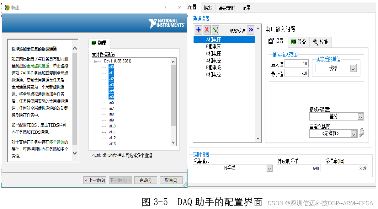
The software operation is as follows: Set the channel name as shown in Figure 3-5. The sampling mode is set to "Continuous Samples," the sampling rate to 3200Hz, and the number of samples to 640. Set the signal input range and wiring method; specific configurations can also be made internally in the program after generating the DAQ Assistant in the block diagram. The configuration interface is shown in Figure 3-5. After the virtual channel configuration is complete, save it in MAX and test the connection between the signal and task channels using the MAX software. If any parameters are configured unreasonably, they need to be modified promptly. The DAQ Assistant should be used within a While loop to ensure continuous sampling.