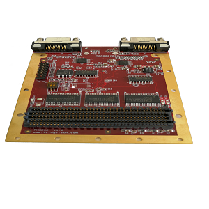
CameraLink HD Medical Imaging Analysis Module
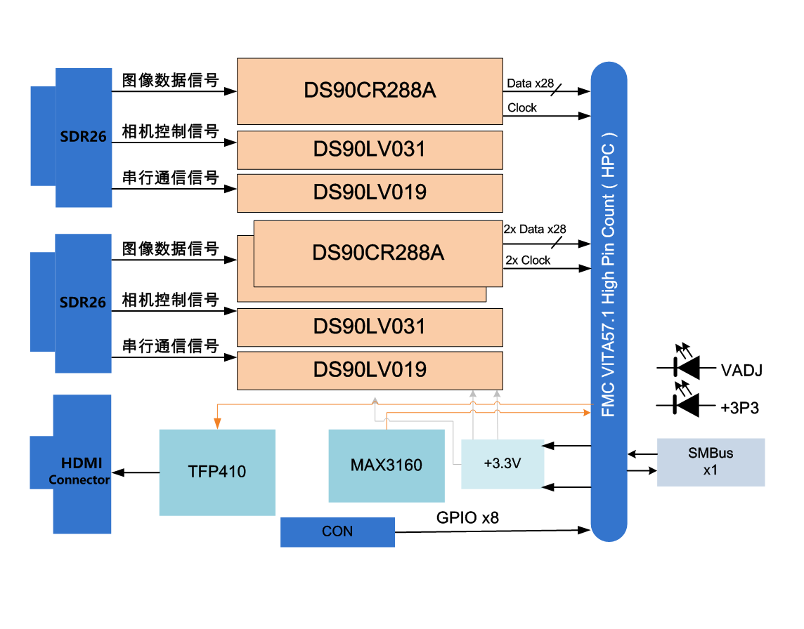
The FMC-XM202 is a sub-card module based on the FMC interface standard, supporting 1-channel CameraLink Full mode (or 2-channel CameraLink Base mode) acquisition and 1-channel HDMI (DVI) video output. This module features two CameraLink ports (SDR, 26-PIN) and can be configured via hardware for 1-channel Full input or 2-channel Base mode input. The CameraLink interface supports 80-bit Deca mode (i.e., Full Plus mode). The module supports 1-channel DVI video output (HDMI connector), with a maximum resolution of 1080P. This module is specifically designed for FMC mezzanine cards, and by pairing it with different FMC carrier cards, a CameraLink video interface-based image analysis and verification platform can be quickly established. It can be widely used in scientific research, education, and the development of high-end video and image products. It is a standard FMC sub-card, compliant with the VITA57 specification.
- Supports 1-channel CameraLink Full mode or 2-channel CameraLink Base mode input
- Supports 80-bit Deca mode (Full Plus mode), with a maximum bandwidth of 850 MByte/s
- CameraLink receiver chip supports a maximum clock frequency of 85 MHz
- Features 1-channel RS232/RS422/RS485 interface
- Features 1-channel DVI display output interface, supporting 1080P resolution
Technical Specifications
- Image Interface Performance:
- Supports 2-channel CameraLink Base digital camera input;
- Supports 1-channel CameraLink Full mode input;
- Supports 80-bit Deca mode, with a maximum transmission bandwidth of 850 MByte/s;
- Two SDR26 connectors, model: 12226-5150-00FR;
- Supports 1-channel DVI digital display output, with a maximum resolution of 1920x1080;
- One HDMI interface, model: 10029449-001RLF;
- FMC Interface Specifications:
- Standard FMC sub-card, compliant with VITA57.1 specification;
- Board dimensions: 84.1 x 69 mm;
- FMC connector model: ASP-134488-01;
- Board powered by +3.3V;
- Three groups of signal lines (X/Y/Z) with equal length design;
- Supports IIC interface;
- CameraLink Channel:
- Decoder chip model: DS90CR288A;
- Maximum operating clock frequency of decoder chip: 85 MHz;
- Other Interfaces:
- One RS422 interface;
- Eight GPIO inputs/outputs;
- Eight LED indicators;
- Physical and Electrical Characteristics
- Board dimensions: 84.1 x 69 mm;
- Board power supply: 0.5A max@+3.3V (±5%);
- Cooling method: Natural air cooling;
- Environmental Characteristics
- Operating temperature: -40°C to +85°C;
- Storage temperature: -55°C to +125°C;
- Operating humidity: 5%~95%, non-condensing;
Software Support
- Optional integrated Board Support Package (BSP):
- Low-level interface drivers;
- Board-level interconnect interface drivers;
- Customized algorithms and system integration can be provided according to customer requirements;
Application Scope
- CameraLink image analysis;
- HD video transmission and processing;
- Medical image analysis and processing;