Design and Implementation of a 1553B Bus Controller Test System Based on ZYNQ 7000
To facilitate the testing of 1553B devices, this paper introduces a design and implementation method for a 1553B bus controller test system based on the ZYNQ 7000 platform. The system first configures data on a PC through a human-machine interface, supporting flexible data fault injection. Then, it sends the data to the ZYNQ's PS (Processor System) side via a serial port. The ZYNQ's PL (Programmable Logic) side reads the data, and finally, the ZYNQ's PL side drives the data out. After the design was completed, simulation verification was performed, and the results showed that it met the design requirements.
Introduction: Avionics systems are distributed communication systems built upon 1553B bus communication networks. Various electronic devices within avionics systems are developed by numerous R&D units according to system requirements and are ultimately integrated into a system via 1553B bus networking. Each R&D unit primarily develops 1553B communication products based on 1553B standard requirements. However, it is challenging for R&D units to thoroughly test 1553B communication products. Furthermore, the design and development approaches, production processes, and test environments for 1553B products vary significantly among different R&D units. This often leads to discovering poor compatibility of certain product specifications only during avionics integration, making integration difficult. This necessitates repeated corrections of original design flaws before integration can be achieved. Even then, potential problems might still exist, resulting in wasted human and financial resources, extended product development cycles, and difficulty in ensuring product quality. This issue directly impacts whether avionics can be smoothly integrated and operate normally.
Currently, most 1553B bus test equipment merely sends correct operational test data to 1553B standard devices for operational testing, offering simple functionality. This test system can inject all error types required by GJB5186-2003 "Digital Time-Division Command/Response Multiplex Data Bus Test Method" into 1553B standard devices, verifying the correctness of their functions.
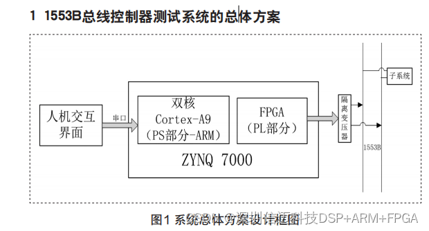
This test system is divided into software and hardware parts. The software part primarily refers to the human-machine interface, whose main functions are to allow test personnel to configure data frames, design test cases, execute test cases, manage data, and review results. After test case execution with the configured data, the PC sends the data to ZYNQ via a serial port. ZYNQ's ARM receives the data, writes it to dual-port RAM, and generates an interrupt flag signal via GPIO. ZYNQ's FPGA, triggered by the interrupt flag signal, reads data from the dual-port RAM and drives the data out according to the protocol.
1.1 Software Design of the 1553B Bus Controller Test System
The software part mainly refers to the human-machine interface, developed using the Eclipse development tool and Java language. The software functions include configuring the number of data frames, configuring data frame content, configuring data words, test case design, test case execution, as well as creating new projects, saving data, and reviewing results. First, configure the number of data frames through the interface, for example, configuring two frames as shown in Figure 2.
Figure 2 Data Frame Schematic Diagram
Secondly, according to GJB5186-2003 "Digital Time-Division Command/Response Multiplex Data Bus Test Method", the following error conditions exist:
(1) Inject odd parity errors into command words, data words, and status words;
(2) Word length errors in command words, data words, and status words (missing 1 bit, missing 2 bits, extra 2 bits, extra 3 bits);
(3) Inject message length errors (incorrect number of data words);
(4) Inject encoding errors into each bit of command words, data words, and status words (missing zero crossing 01->00 or 10->11, polarity inversion 01->10 or 10->01);
(5) Synchronization header encoding errors in command words, data words, and status words (inject invalid synchronization headers: 'b111100, 'b110000, 'b111001, 'b011000, 'b000111, etc.);
(6) Inject data discontinuity errors (insert time intervals between adjacent data);
(7) Terminal fault (ability to safely handle a message timeout condition).
Based on the above fault conditions, the design interface is shown in Figure 3, allowing flexible configuration of data fault conditions.
Then, perform test case design, selecting which frame to send and adding delay control between frames, as shown in Figure 4.
Xinmai provides ZYNQ + 1553B solutions.