Key Technology Research and Development of a ZYNQ+Linux+Xenomai-based Multi-axis Motion Control Platform - Test System Setup (Part 4)
This chapter describes the setup of the experimental test platform to test the hardware functions and system task communication functions of the multi-axis motion control platform. Through the test results, the correctness of the platform's hardware design is verified, and the functionality and performance of the system's real-time processing and synchronous control are validated.
5.1 Test Platform Setup
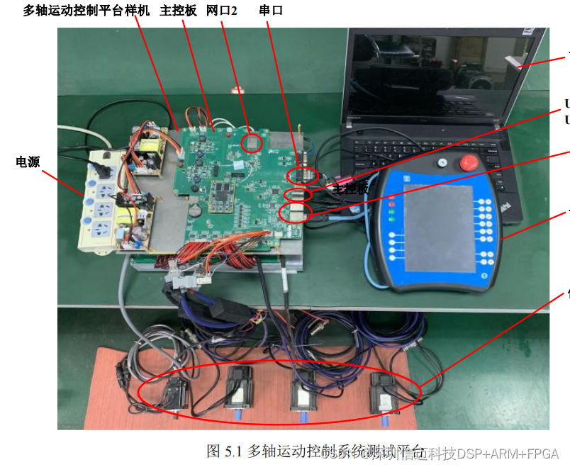
The test platform setup for the multi-axis motion control system is shown in Figure 5.1. The test platform consists of a safety power supply, a multi-axis motion platform prototype (including the main control board MC), a host PC, a handheld pendant, and four 80ST-M0 1330LMB Huada AC servo motors (with built-in 17-bit absolute encoders). The prototype is connected to the four servo motors via motor power interfaces and encoder interfaces.
Hardware testing of the motion control platform mainly includes functional tests for UART serial ports, USB 2.0, and Ethernet interfaces. Task communication testing for the platform system comprises two parts: functional implementation and performance. Specifically, functional testing verifies whether periodic and aperiodic task communication between dual cores is properly implemented. Performance testing examines the real-time capability and synchronous control function of the motion control system. Finally, the robot control software is run on the platform and connected to the handheld pendant to test the overall system operation.
5.2 Motion Control Platform Hardware Function Testing
5.2.1 UART Interface Test
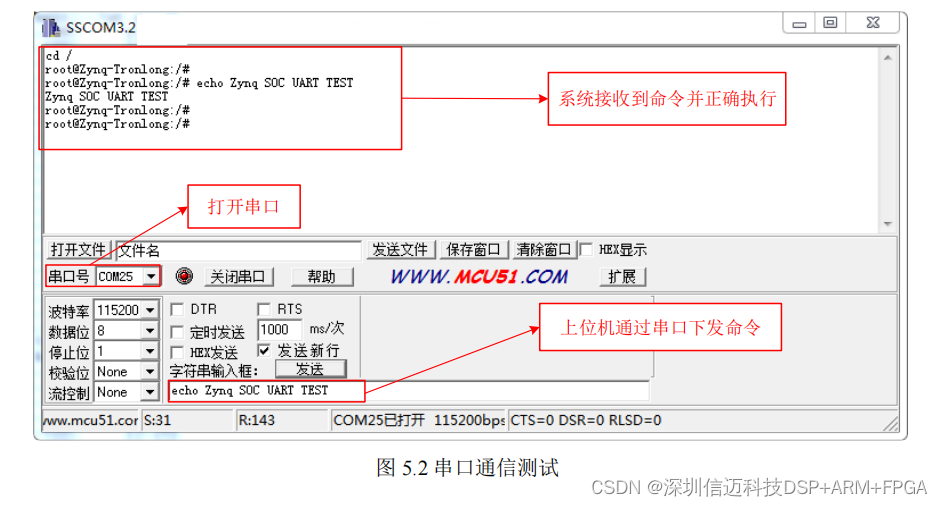
The control platform is connected to a Windows host via the UART interface, and serial port testing is performed using SSCOM3.2 software. As shown in Figure 5.2, the platform's UART interface is correctly recognized as COM25 in Windows. The serial port is opened in SSCOM software, and commands are sent to the Linux system. Observation through the message window shows that the Linux system correctly received and executed the commands. The test results indicate that the system's UART interface functions normally.
5.2.2 USB Interface Test
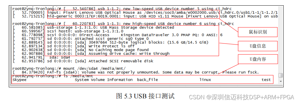
The platform has two USB 2.0 interfaces, which are tested individually for functionality. Interface USB0 is connected to a mouse, and interface USB1 is connected to a USB flash drive. As shown in Figure 5.3, the Linux system correctly recognized the mouse and USB flash drive devices. By mounting the USB flash drive using the mount command, its files can be viewed. The test results indicate that the system's USB interfaces function normally.
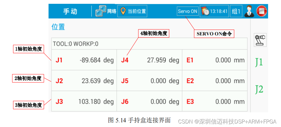
After the robot control software is running, the motion control platform communicates with the handheld pendant via a Gigabit Ethernet interface. First, the IP address of the handheld pendant is set to 192.168.1.114 to establish a network connection with the control platform. After the handheld pendant is successfully connected to the motion control platform, the servo system is enabled using the "SERVO ON" command, and the initial positions of the motion platform's four axes are read. As shown in Figure 5.14, the handheld pendant software reads the initial angles of the four axes, which are consistent with the data from the robot controller software. The test results indicate that the robot control software runs normally on the platform, and the platform successfully establishes connection and communication with the handheld pendant.