FPGA Algorithm Implementation of a Shaker Controller Based on Zynq+AD+DA (Part 3)
4 FPGA Implementation of Shaker Control Algorithms
4.1 PID Control Algorithm
4.1.1 Incremental PID Control Algorithm
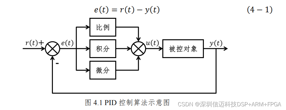
PID control is a widely used control method in control engineering [33]. Its basic principle block diagram is shown in Figure 4.1, where 𝑢𝑢(𝑡𝑡) is the control signal, 𝑟𝑟(𝑡𝑡) is the system input signal, and 𝑦𝑦(𝑡𝑡) is the system output signal. The control system is mainly composed of three components: Proportional, Integral, and Differential. The system error is processed by the three units of the controller through operations and linear combination to obtain the control quantity, where the system error 𝑒𝑒(𝑡𝑡) can be expressed as
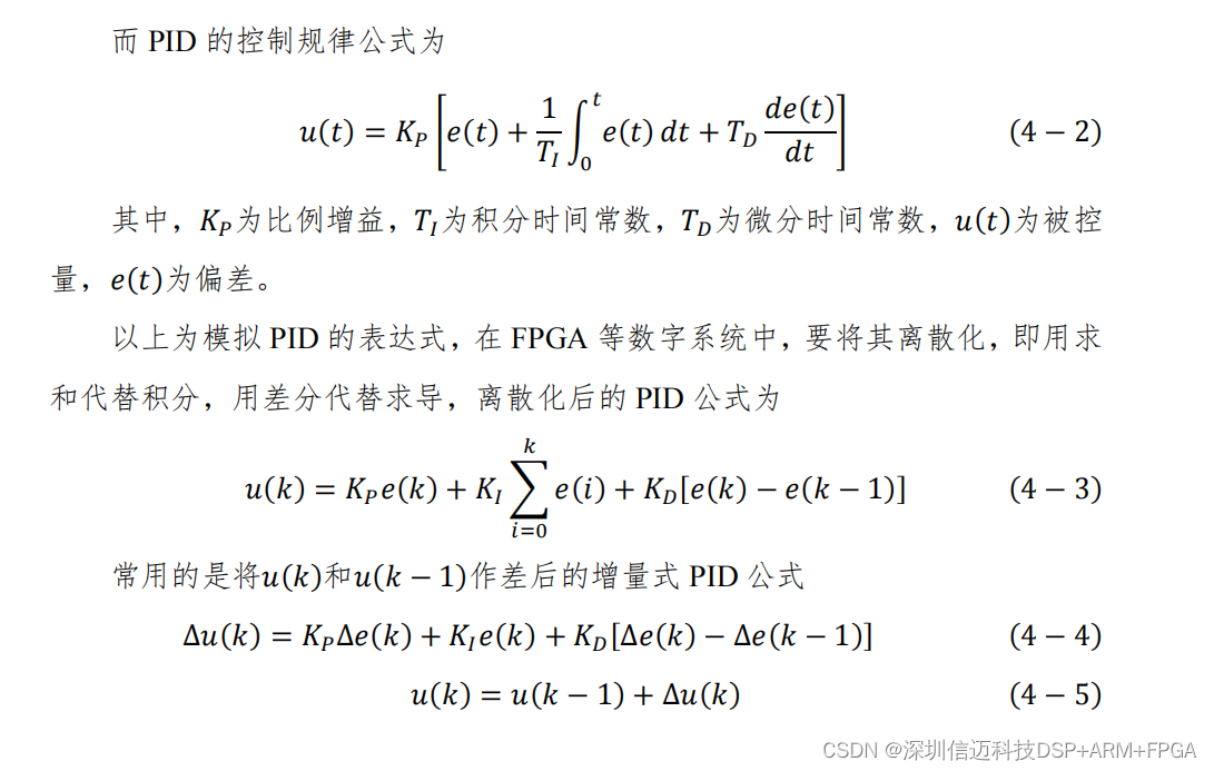
As can be seen from the above equation, the incremental PID is only related to the errors of the previous three times. It does not require storing a large amount of data for summation, making the implementation method relatively simple and very suitable for use in digital control systems [34–36]. The flowchart of the incremental PID algorithm is shown in Figure 4.2 [37–39].
4.1.2 FPGA Implementation of PID Control Algorithm
In Verilog, the transformation of equation (4-7) can be performed using combinational logic.
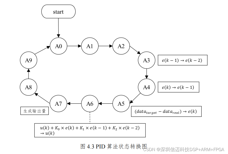
The state transition diagram for the PID algorithm implementation is shown in Figure 4.3.
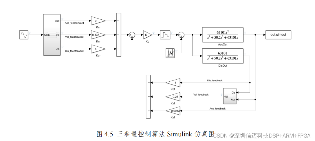
4.2.2 MATLAB/Simulink Simulation of the Three-Parameter Control Algorithm
To verify the feasibility of the three-parameter control algorithm and to provide a reference for subsequent parameter tuning, a simulation was conducted in MATLAB/Simulink [44,45], as shown in Figure 4.5.
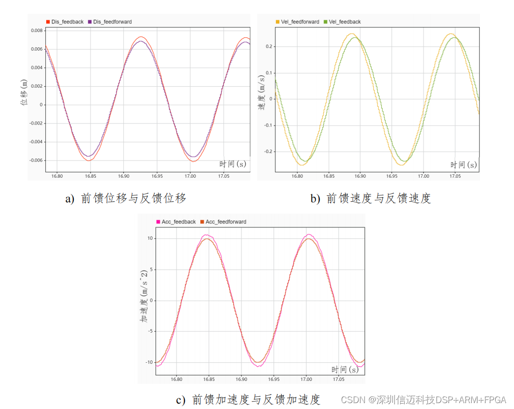
When the input sinusoidal reference waveform (acceleration) has an amplitude of 10 and an angular frequency of 40 rad/s, the displacement, velocity, and acceleration waveforms for feedforward and feedback are obtained as shown in Figure 4.6.
4.2.3 FPGA Implementation of the Three-Parameter Control Algorithm
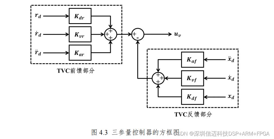
There are two key points in the implementation of the three-parameter control algorithm: the synthesis of velocity feedback and the generation of feedforward quantities. Feedforward quantities can be synthesized from one reference signal to generate the other two signals, or three reference signals can be directly input. For convenience, reference displacement, reference velocity, and reference acceleration were directly downloaded from an earthquake database and input into the system as feedforward signals. Therefore, the focus will be on discussing the synthesis of velocity feedback.
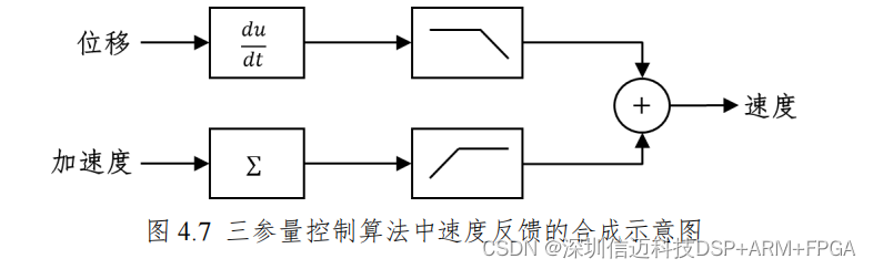
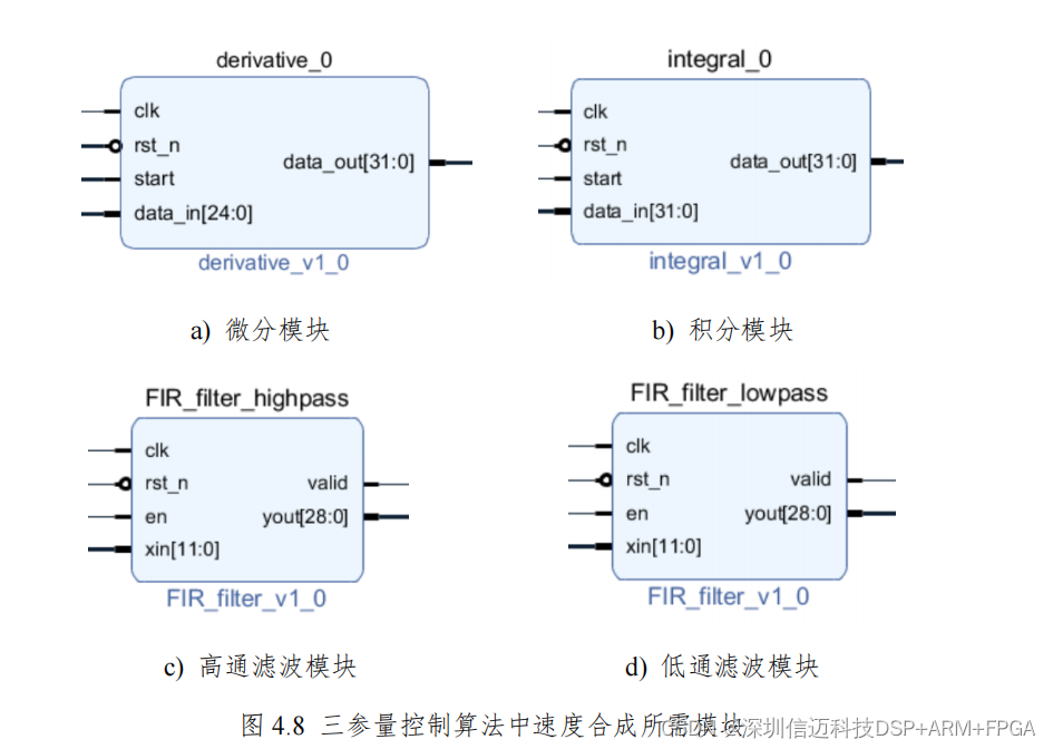
In shaker systems, generally only displacement sensors and accelerometers are available. Therefore, velocity needs to be synthesized using displacement differentiation or acceleration integration [46–49]. Here, a combination of both methods is adopted. Velocity is obtained by differentiating displacement and then low-pass filtering, and integrating acceleration and then high-pass filtering, and then summing the two results, as shown in Figure 4.7. The implementation block diagram of the specific module is shown in Figure 4.8.
This chapter introduces two commonly used control algorithms in shaker control systems—the PID algorithm and the TVC algorithm. They are implemented in FPGA and integrated into the program architecture of the Zynq controller. Each algorithm module can be easily added to the program architecture, and control algorithms can be switched by issuing commands from the host computer. To provide a basis for subsequent parameter tuning, simulations were also conducted in Simulink. More algorithm modules can be added later to meet the requirements of more vibration testing scenarios.
Xinmai provides customized ZYNQ controller solutions.