Vibration Table Controller Architecture Design and Algorithm Implementation Based on Zynq + AD + DA - Overall Architecture Design (Part 1)
Electro-hydraulic vibration tables can simulate vibrations in real-world environments and are widely used in fields such as seismic simulation for buildings, material structure testing, automotive testing, and marine gangways. High-performance vibration controllers required for controlling electro-hydraulic vibration tables primarily rely on imports. In recent years, FPGA-based vibration controllers have begun to highlight their advantages, making them more suitable for multi-channel, high-frequency, and other testing scenarios.
This paper designs a set of vibration table control programs based on the CPU+FPGA architecture of the Zynq-7000 chip, which is clearly structured, highly versatile, and easily extensible. It implements functions such as data acquisition, control, and Ethernet communication. System tests were conducted to verify the rationality and effectiveness of the controller architecture. Sine wave tests and seismic wave tests were performed. In the sine wave tests, the displacement correlation coefficient and acceleration correlation coefficient reached 99.86% and 94.87% respectively, while for the seismic wave tests, they reached 99.998% and 65.68% respectively.
1.3 Introduction to Zynq-7000 Chip
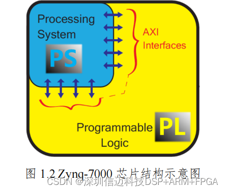
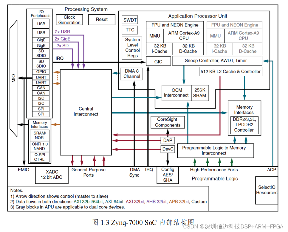
The Zynq-7000 is an ARM CPU+FPGA architecture SoC chip manufactured by Xilinx [16]. It uses a 28nm process technology. It is divided into two parts: the Processing System (PS) and the Programmable Logic (PL) [17]. The PS part is a dual-core ARM Cortex A9 processor capable of running full operating systems like Linux, while the PL part is an FPGA architecture based on the Xilinx 7 series (Artix-7/Kintex-7). A high-bandwidth, low-latency connection is achieved between the two via AXI interfaces. Both the processor and logic parts can achieve optimal performance independently, and a single-chip solution also leads to reduced physical size and overall cost [18].
Zynq-based controllers offer the following advantages:
(1) Architectural Advantages. Thanks to Zynq's ARM+FPGA architecture, the controller's core functions can be developed as two parts: software and hardware. Software and hardware work collaboratively to control the vibration table. Parts requiring high real-time performance and computational power, such as sampling, computation, and control, are handled by the hardware logic (PL), while parts with lower real-time requirements, such as communication, are handled by the software (PS).
(2) Parallelism Advantages. The inherent parallelism of the FPGA portion makes Zynq-based controllers suitable for multi-channel collaborative control, enabling more real-time and precise control.
(3) Frequency Advantages. The clock frequency on the PL side of the Zynq chip can reach up to 250MHz. The control frequency for a typical PID algorithm (calculated assuming a pipelined design where one control cycle completes in 2 clock cycles) is expected to reach up to 125MHz.
MIO (Multiplexed I/O) is fundamental for I/O peripheral connections. The number of MIO pins in the Zynq-7000 SoC is limited, totaling 54. I/O signals can be connected to MIO pins through configuration. Furthermore, I/O peripherals within the PS can also be connected to the PL via the EMIO (Extended MIO) interface. As shown in Figure 1.5, this allows I/O peripheral controllers within the PS to connect with user-defined logic in the PL, facilitating PS access to more device pins and interaction with PL-side logic resources.
2 Overall Design of the Vibration Table Control System
A vibration table control system is a complex mechatronic system integrating mechanical, hydraulic, electronic, control, and computer hardware/software. The design goal of a vibration table control system is to make the vibration table surface move according to a desired waveform.
Firstly, to achieve sufficient motion range and adequate motion speed and acceleration, a mechanical system that meets motion requirements and a hydraulic system that provides the power source are needed. The response time of the entire mechanical and hydraulic system must also be sufficiently fast. Secondly, for convenient human-machine interaction, primarily real-time waveform display and real-time modification of control parameters, corresponding host computer software and matching programs in the lower-level controller are required. Finally, to achieve precise motion control, high-precision hardware circuits centered on data acquisition, control, and output are needed, along with accompanying control programs centered on data acquisition, data processing, control algorithms, and output drivers.
The mechanical and hydraulic systems are primarily developed by partner companies and are not the focus of this research. This chapter will introduce the host computer software, hardware circuit board, and the design objectives for the Zynq controller program, respectively. Subsequent chapters will focus on the design of the controller program.
2.1 Host Computer Software Function Overview
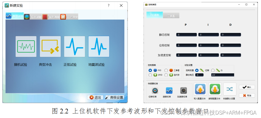
The main interface of the host computer software for the vibration table control system is shown in Figure 2.1. This host computer software can implement the following functions: generation and transmission of reference waveforms; real-time display of reference and actual waveforms, including displacement, velocity, and acceleration; setting and transmission of control parameters; export of experimental data; and some basic data analysis.
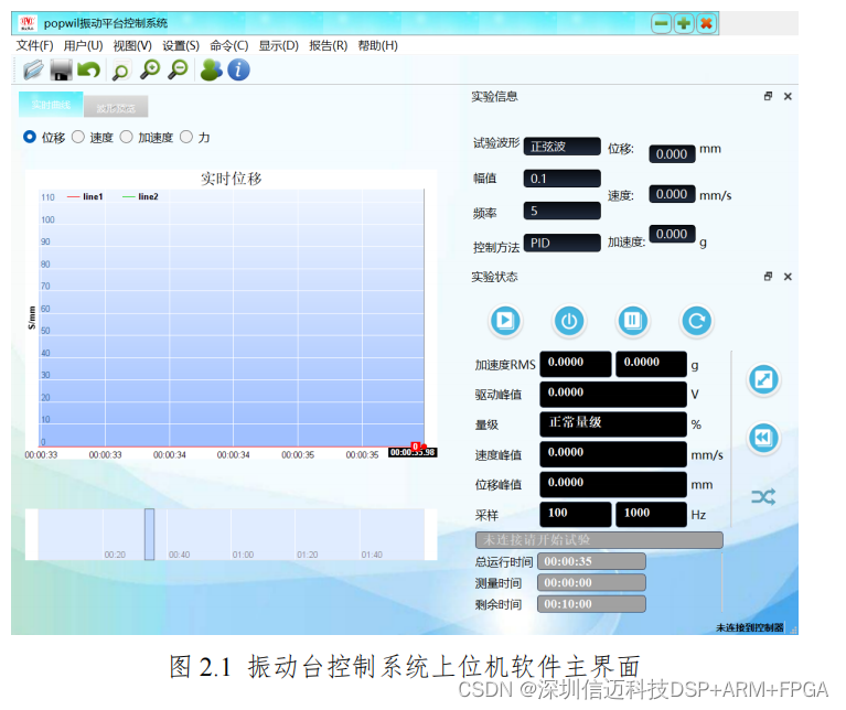
etc. [21]. The Ethernet communication function among these needs to be completed in conjunction with the Zynq controller. There will be extensive interaction between the two, which is a bidirectional communication process.
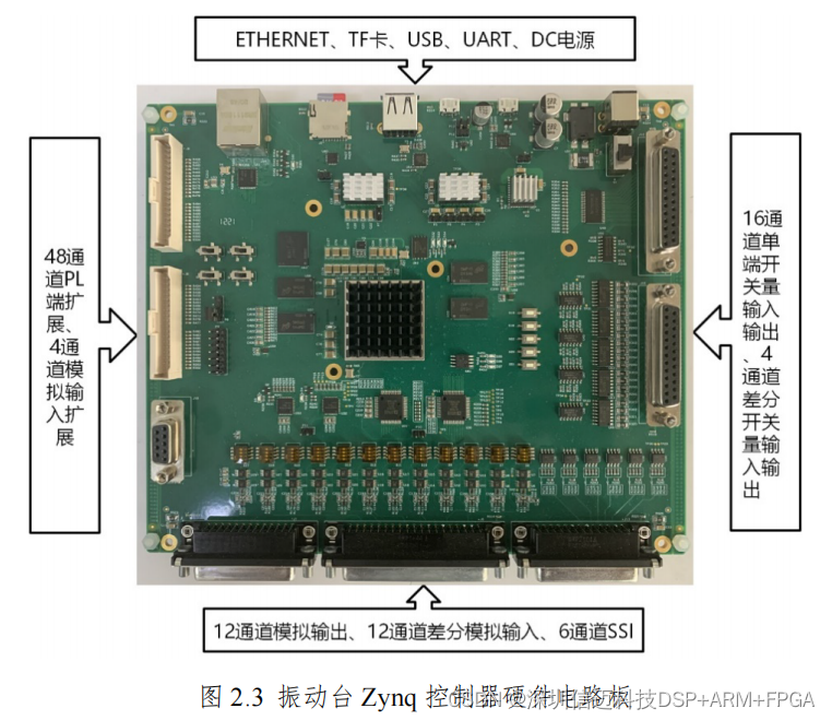
2.2 Hardware Circuit Board Function Overview
The vibration table Zynq controller references Xinmai's ZYNQ board. The hardware circuit is mainly divided into several major modules: Zynq core module, power management module, input module, output module, storage module, and communication module [22]. Among these, the communication module is responsible for Ethernet communication with the host computer software. The input module is responsible for acquiring actual motion data, including SSI digital signals from displacement sensors, analog voltage signals from acceleration sensors, analog voltage signals from force sensors, etc. The output module is primarily responsible for outputting control voltage, which then passes through a voltage-to-current module to drive the hydraulic servo valve, causing the actuator to operate.
2.3 Objectives of Zynq Controller Program Design
Combining the requirements of the entire vibration table control system with the existing conditions of the host computer software and hardware circuits, the target functions for the Zynq controller program design are summarized as follows:
① Data acquisition and processing functions, mainly including the acquisition and processing of SSI digital signals and ADC data;
② Output driving, primarily referring to driving DACs;
③ Ability to form basic feedback control loops, supporting configurable parameters;
④ Ethernet communication function with the host computer software, mainly including receiving reference waveforms, uploading reference and actual waveforms, and receiving and implementing parameter modification commands.
Xinmai provides customized ZYNQ controller solutions.