Software Design of a Multi-Parameter Data Recorder Test Platform Based on RK3399 + Linux QT
With the increasingly critical role of high-tech in modern warfare, the development of flight equipment has evolved from single-system to multi-system architectures. During the design of aviation systems, extensive testing is required—especially the real-time recording of operational status parameters across various subsystems during development and flight testing—for subsequent analysis and design improvements. Data recorders have thus emerged to meet this need. A data recorder is a storage and measurement device that conditions, acquires, processes, and records various onboard signals before, during, and after missile launch. After the missile completes its mission, data stored in the recorder's memory can be recovered via specialized methods. Emphasizing testing technologies effectively reduces development risks, saves R&D costs, and shortens development cycles. Therefore, testing technology is an essential component in the development of flight systems.
The ground test station serves as a supporting test device for a specific model of data recorder. Its primary functions include: performing pre-flight functional checks on the recorder to verify its operational status and stability; and after experiments, retrieving and further processing data stored in the recorder. Through data analysis, changes in various missile parameters during flight tests can be determined, providing feedback on the missile’s performance. Hence, the stability and data processing capability of the ground test station play a crucial role in missile research. This chapter begins with requirement analysis, conducts an overall assessment of the recorder’s main tasks, and establishes the overall design scheme.
2.1 Task Requirement Analysis
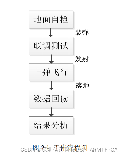
Figure 2.1 shows the workflow of the data recorder. All steps in the diagram except the third require participation from the ground test station. Based on the operational requirements of the recorder, the test station software primarily implements ground self-test and data retrieval with display functionality. The software must support data reading and clearing, parameter configuration, and device diagnostics. Communication interfaces use both serial and Ethernet ports for command transmission and data retrieval. The main tasks the test station software must fulfill include:
- Ground self-test. Before flight testing, the test station simulates real data: the host computer controls the main CPU to generate simulated data, stores it into the recorder, then retrieves it. By comparing the retrieved data with the original simulated data, the operational status of the recorder is verified. Two operation modes—manual and automatic—are available, controlled via serial commands from the host computer at a baud rate of 57,600 bps. Each data channel has a corresponding LED indicator on the test station. Data format: Header + Frame Count + Data + Checksum. Table 2.1 details the simulated data, including the following types:
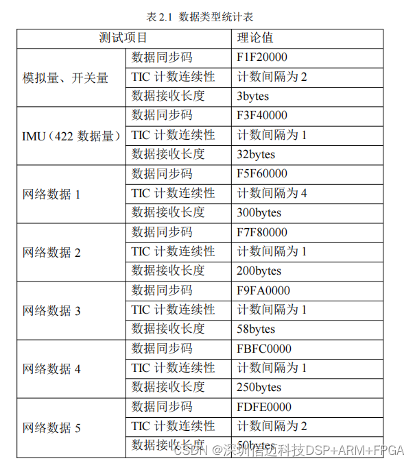
a) One channel of 422 digital signal source: 57 bytes, baud rate 460.8 kbps, frequency 200 Hz;
b) Two channels of analog signal sources;
c) Five channels of switch signal sources;
d) Five channels of Ethernet data signal sources, where Network Data 1 operates at 50 Hz, Network Data 2, 3, and 4 at 200 Hz, and Network Data 5 at 100 Hz.
-
Support UDP-based data retrieval. Data retrieval uses the UDP network transmission protocol, with files saved in .hex format.
-
In data retrieval mode, support primary/backup memory selection and status queries (e.g., power-on count and storage capacity) via commands;
-
In data retrieval mode, read stored information via a side monitoring port, using files (or blocks) as the unit, and save the data to the host computer;
-
In data retrieval mode, support erasing data recording devices (full erase), with confirmation required before erasure.
-
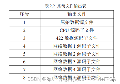
Data separation. Based on different frame headers per channel as shown in Table 2.1, separate the retrieved data according to their respective headers, ultimately generating one source file and seven sub-data files. These files are exported via USB for further analysis and processing. Table 2.2 shows the system file output list.
2.2 Overall System Design
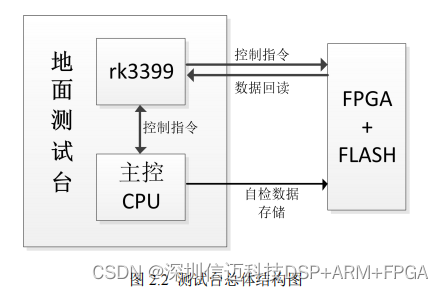
Based on the test station's task requirements, Figure 2.2 illustrates the functional architecture of the test station and the data recorder. The RK3399 serves as the host computer of the test station system. It communicates with the main control CPU via serial commands to control the test station’s power system. It also sends commands to generate simulated data, which the main CPU transmits and stores into the Flash memory chip of the recorder. Finally, data is retrieved using the UDP network protocol. The development board is embedded within the test station and connected to a small LCD screen for displaying the software interface.