Design of a Multi-axis Motion Controller Based on STM32+FPGA
Motion controllers are the core of control systems for automated equipment such as CNC machine tools and high-end robots. To ensure the practicality, real-time performance, and stability of the controller, a multi-axis motion controller design scheme is proposed, using STM32 as the main controller and FPGA as the auxiliary controller. The hardware circuit design of the motion controller is presented, and an S-curve acceleration/deceleration algorithm is integrated into the motion controller, improving control precision and effectively preventing phenomena such as overshoot and oscillation. The performance of the motion controller was tested on a 3D dispensing machine platform, and the results show that each axis of the dispensing machine can move according to the set trajectory, operating smoothly with high real-time performance, demonstrating good application prospects.
The performance of motion controllers directly determines the overall performance of automated systems [1-2]. Companies like Chrysler, Siemens, FANUC, and MAZAK occupy about 90% of China's industrial motion controller market. With the development of motion control technology, FPGAs, ARMs, DSPs, and dedicated chips have gradually become core components of motion controllers and are increasingly moving towards an open architecture [3-4]. Motion controllers based on microcontrollers have slow computation speeds and low control precision, generally used in low-speed applications with simple motion trajectories; motion controllers based on dedicated chips only output pulse signals, cannot receive feedback signals, operate in an open-loop state, and cannot meet the requirements for multi-axis linkage and high-speed, high-precision trajectory interpolation [5-7]. PC-based motion controllers with FPGAs, ARMs, and DSPs as core processors, such as Googol Technology's GH-800, offer fast data processing speeds and high real-time performance, capable of multi-axis coordinated control, complex trajectory motion, and acceleration/deceleration. Using STM32 as the main controller and FPGA as the auxiliary controller, a hardware platform is built and peripheral circuits are designed. Leveraging STM32's rich peripheral resources, it handles motion trajectory planning, human-machine interaction, data storage, data exchange, and other controls; utilizing FPGA's abundant logic resources, it achieves parallel pulse output for each motion axis, detection of input signals and home positions, and digital output control. The S-curve acceleration/deceleration algorithm is introduced into the controller design, which effectively avoids phenomena such as overshoot, step loss, and oscillation during actual operation. This motion controller has a simple hardware structure and can effectively shorten the development cycle while ensuring precision, real-time performance, and reliability.
1 Motion Controller Structure
The motion controller adopts an STM32+FPGA hardware architecture, with STMicroelectronics' STM32F4xx chosen as the main control chip and Altera's EP2 series chip as the auxiliary control chip. The main modules include a data storage module, external input detection module, motor drive module, interface module, human-machine interaction module, etc. Its block diagram is shown in Figure 1.
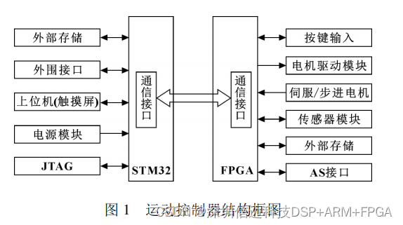
The main controller, centered around STM32, stores data from the motor operation process into external memory and implements human-machine interaction using a combination of a touchscreen and buttons; the touchscreen acts as the host computer, communicating with the STM32 via a serial port for system debugging, while buttons are connected to the FPGA via I/O interfaces. After the main controller processes the interpolation information from the external data memory, it sends it to the FPGA via a bus. Upon receiving control commands or interpolation data, the FPGA performs interpolation calculations, then sends signals to each motor driver through isolation circuits to drive the respective axis motors, completing the target motion trajectory.
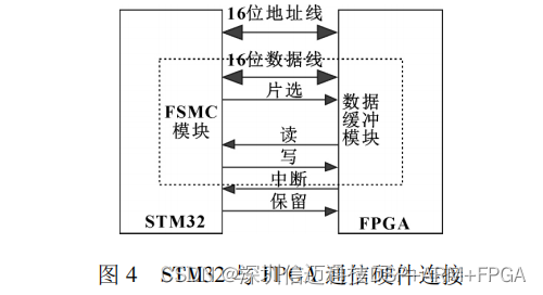
STM32 and FPGA Communication Interface
Communication between STM32 and FPGA can be achieved via the Flexible Static Memory Controller (FSMC), as shown in Figure 4. Based on the functional characteristics of FSMC, the address and data bus width of STM32 are set to 16 bits. STM32 selects the FPGA via chip select for data reading and writing, and the FPGA provides feedback on data processing status via interrupts.
STM32 Chip Configuration
The external hardware watchdog of the STM32 chip can effectively monitor the CPU's operation. STM32 requires two external crystal oscillators: one with a frequency of 32.768 kHz, primarily providing a low-speed, high-precision clock to the chip's internal clock components; and another with a frequency of 25 MHz, generating the main clock, which is then supplied to various modules after passing through frequency division and multiplication modules [4, 6].
2.2 FPGA Module Circuit Design
The FPGA is primarily responsible for processing interpolation algorithm information, outputting pulse signals, inputting and outputting digital signals, and receiving differential signals from encoders.
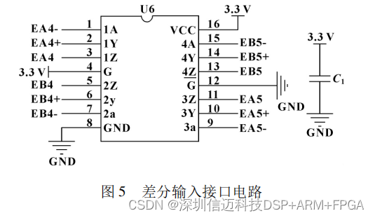
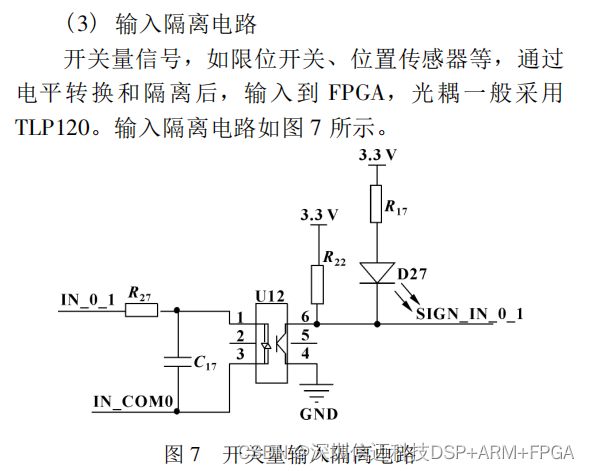
(1) Differential Input Interface Circuit
U6 is a four-channel differential signal receiver, used to receive differential signals output by the encoder and feed back motor position information to the FPGA. The interface circuit is shown in Figure 5.
3 Motion Controller Software Design
Instructions are sent to the STM32 via the touchscreen (HMI). Upon receiving instructions, the STM32 stores them in external memory using a dynamic linked list; the memory is read in real-time, and the position and velocity information of the motion axes are returned to the touchscreen for display. Simultaneously, instruction information and interpolation algorithm data are transferred to the FPGA via FSMC for processing; finally, a pulse generator generates pulse commands for the motor drivers, causing the motors to rotate. The block diagram of the motion controller software design is shown in Figure 8.
![](https://pub-048dcb96257f476697b113fcb5939cb9.r2.dev/blog/129003308/06_ba4a50712b85b5cc092043d4ff2b17b