Research on Flexible Printed Circuit Board Defect Detection Methods
Research on FPC Defect Detection Methods Based on Template Matching
Template matching, as the most intuitive and fundamental pattern recognition method, is widely applied in fields such as object recognition and artificial intelligence. It is an effective approach for circuit board defect detection, essentially measuring the similarity between a registered FPC image and an inspection FPC image. This chapter investigates the FPC board defect detection process from the perspective of template matching.
Template matching methods can be classified in various ways. Based on the scope of template matching, they can be categorized into two types: global matching and local matching [8]. Global template matching treats the deviation of the inspection template relative to the registered template as a spatial image shift, and the entire image is corrected based on this shift. In contrast, for local template matching, the obtained offset is considered only as the spatial shift of the current template, and the detection of the entire image is ultimately achieved by detecting local templates.
2.1 Research on FPC Defect Detection Methods Based on Global Matching
Global template matching treats the image as a whole, where the offset obtained from template matching represents the spatial shift between images. The core challenge is determining the reference points for the image coordinate system. Based on the number of reference points, methods can be classified into single-reference-point matching and multi-reference-point matching.
2.1.1 Research on FPC Defect Detection Methods Based on Single Reference Point Registration
For image registration based on a single reference point, the reference point should possess universality. In FPC image manufacturing, the fiducial marks have distinct shape features and defined regions, making them suitable as image reference points.
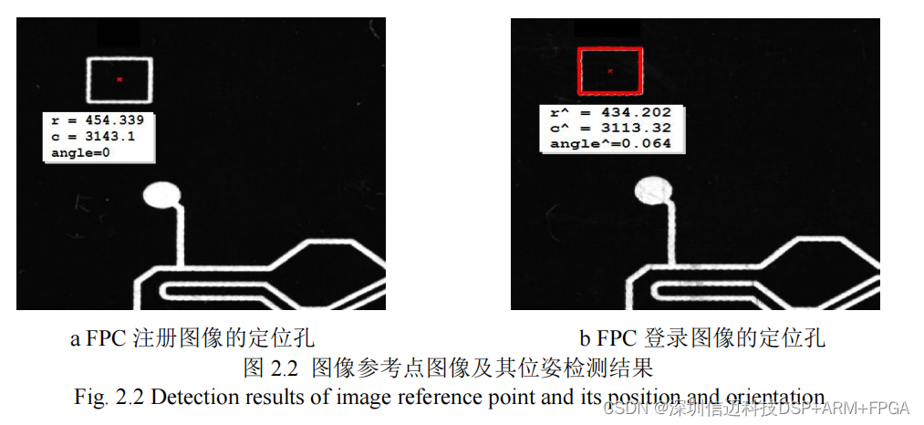
Due to size variations in fiducial marks across different board types, this section employs template matching to locate image reference points and subsequently perform defect detection. The process involves first extracting the reference point pattern from the registered image to serve as the registration template. Then, during the determination of the inspection image's reference point, template matching is used to detect the pose of the reference point in the inspection image, yielding the difference in coordinate information between the two reference points. Based on this difference, the image is corrected. Finally, image differencing is performed to obtain circuit defect information, completing the defect detection process. The specific steps are as follows:
(1) Obtaining the Reference Point Image During Registration
Template matching requires the preparation of a registration template beforehand, and its creation varies depending on the specific template matching method. Given that FPC image circuit shapes are relatively simple, contour-based template matching methods demonstrate good recognition rates under occlusion, clutter, or unstable lighting conditions [14-16]. Therefore, this paper adopts a contour-based template matching method. The process for obtaining the registered reference point is as follows:
- Determining the Region of Interest (ROI)
The fiducial marks on FPC patterns exhibit distinct rectangular features, as shown in the circuit diagram in Figure 2.1(a). Based on prior knowledge, a Region of Interest (ROI) containing the fiducial mark is pre-selected. To prevent noise interference, the optimal ROI size is just large enough to encompass the fiducial mark, as shown in Figure 2.1(b).


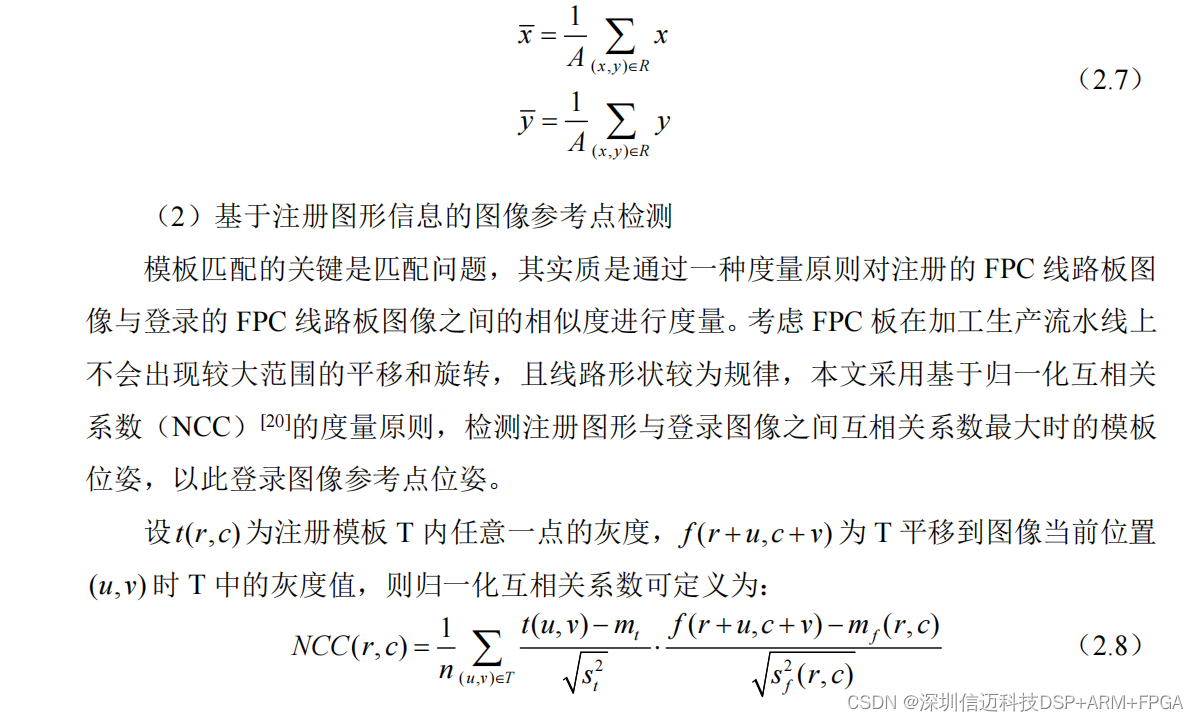
The rectangular contour region obtained using the Canny operator serves as the graphical feature of the reference point during registration. The reference point graphic and its region's center coordinate information are backed up for later use. The region center is the geometric centroid of the image. Let R be the region under consideration, and A be the number of pixels in the region (i.e., the area). Then the center of region R can be expressed as:
(4) Image Differencing Operation [25] for Locating Defect Information
Image correction ensures the spatial alignment of the two images. Through a simple image differencing operation, the resulting difference image provides an effective description of circuit defect information, as shown in Figure 2.3. Ideally, with perfect registration of the two images, the grayscale value of the difference image should be 0. Considering the influence of illumination on image grayscale, good matching implies that the grayscale variation in the difference image approaches a constant.
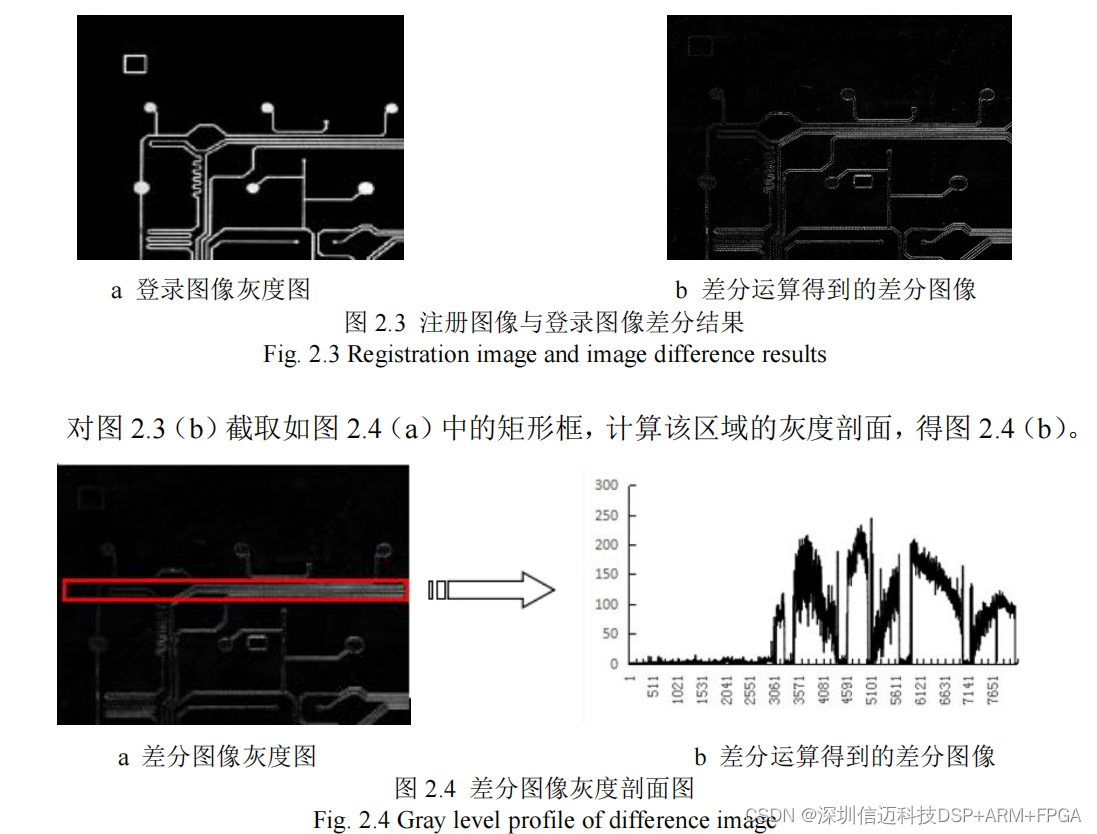
From the grayscale profile above, it can be observed that the grayscale distribution of the difference image is uneven, exhibiting inconsistent brightness and deformation. Moreover, after image differencing, grayscale values can still exceed 200, which is unfavorable for subsequent defect segmentation.
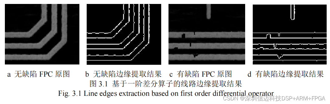
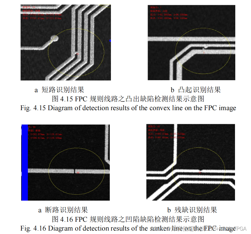
Figure 3.1 displays the image edges extracted using directional templates when the threshold is set to 80. As shown in the figure, circuit edges extracted using a first-order differential operator retain important information about image edge discontinuities. Building upon this, defect information can be located by tracking changes in edge line width and comparing them with pre-defined line width thresholds [31]. Defect localization was performed on Figure 3.1(d), and the results are presented in Figure 3.2(a). In Figure 3.2(a), red pixels indicate the identified defect locations.