High-Speed High-Precision Semiconductor Motion Stage Design (Part 2)
The performance of high-speed, high-precision motion platforms is not only related to the motion controller and servo drives but also closely linked to the performance of the motor itself. The motion platform shown in Figure 5-2 utilizes Yaskawa linear motors, which directly drive the load, offering high rigidity and fast response. Concurrently, a high-performance multi-axis motion control card and GTHD series high-performance servo drives were selected as the platform's servo control system.
X-Y Motion Platform Position Detection Device
The accuracy requirements for high-speed, high-precision motion platforms are at the μm level, which necessitates the selection of high-resolution detection devices. Commonly used position detection devices for linear motors include lasers, magnetic scales, inductive synchronizers, and optical encoders. Laser devices, as detection devices, offer high accuracy and stability but come at a high cost. Both magnetic scales and inductive synchronizers are based on the principle of electromagnetic induction; they are low-cost but unstable and prone to interference. Considering both cost and reliability, selecting optical encoders as the position detection device is the most suitable option.
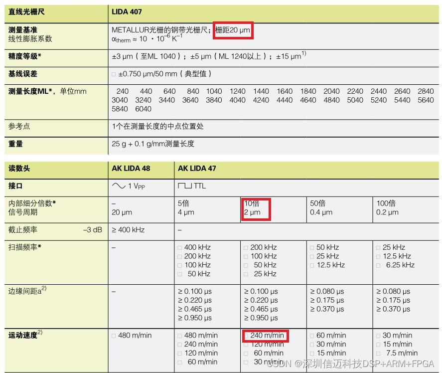
An optical encoder scale consists of two parts: a main scale grating and an index grating, with the index grating typically installed in the read head. The surface of the grating is engraved with uniform, parallel stripes, where the distance between the stripes (grating pitch) d is equal. After installation, the main scale grating and the index grating are placed parallel to each other, with a small angle θ formed between their stripes. Under illumination from a light source, alternating bright and dark fringes, known as "Moiré fringes," are formed. When the main scale grating and the index grating move relative to each other by one grating pitch, the Moiré fringes also move by one fringe distance. Since the variation pattern of Moiré fringes approximates a trigonometric function, by counting the Moiré fringes, the relative displacement between the main scale grating and the index grating can be measured, thus determining the platform's travel distance. The installation method for optical encoder scales is relatively flexible, allowing them to be mounted at different positions on the motion platform. As shown in Figure 5-1, the read heads of the optical encoder scales for the two motion axes of the X-Y motion platform in this project are fixed relative to their direction of motion, while the main scale gratings are installed on the moving parts. The X-Y platform studied in this project uses Heidenhain's LIDA477 series optical encoder scales. The specific parameters of the optical encoder scale are shown in Figure 5-3. The grating pitch of the optical encoder scale is 20_μm_, and with a 10x interpolation factor, the resolution is 2_μm_. The maximum speed is 4_m/s_. Through the driver's 4x frequency multiplication technology, the platform's measurement resolution is 0.5_μm_.
Motion Control System Composition
The control system for the X-Y motion platform, which is the subject of this study, comprises two parts: hardware and software. The hardware part mainly consists of an industrial PC, a motion control card, drives, and the X-Y motion platform. The software part mainly includes host computer software and underlying servo control algorithms.
- Motion Control Hardware
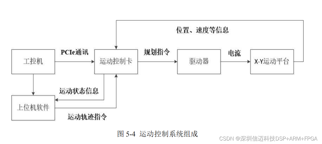
Motion control cards typically communicate with an industrial PC via PCI/PCIe interfaces, thereby receiving commands sent by the host computer software and sending motion planning commands to the drives. The drives perform calculations, amplification, and other processing, ultimately outputting current to the linear motors to make the motion platform move. The control system diagram is shown in Figure 5-4.
- Motion Control Software
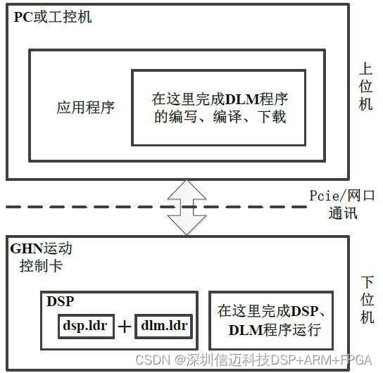
The motion control software primarily consists of two parts: underlying control algorithms and upper-level interface software. The underlying control algorithms are developed based on the DLM functionality of the motion control card, using Analog Devices' DSP development environment CCES2.8.0, and are mainly used to implement servo control calculations. The most significant feature of DLM is that it allows users to customize control algorithms and planning algorithms within the DSP. The upper-level interface software is developed using MFC within the Visual Studio 2013 development environment. It is primarily used to provide a user-friendly human-machine interface and to complete tasks such as control parameter settings, motion debugging, data display, and data storage. This project developed an X-Y motion platform debugging software, which is the upper-level interface software for the motion control software. A screenshot of the software interface is shown in Figure 3-7. For specific software functions, refer to Section 3.3.2.
The functional structure of the motion control software is shown in Figure 5-7. dsp.ldr is the firmware for the motion control card, supporting various commands of the motion control card. dlm.ldr contains the servo control algorithms and motion planning algorithms developed in this project.