Wafer-Level Flip Chip Bonder and Control System
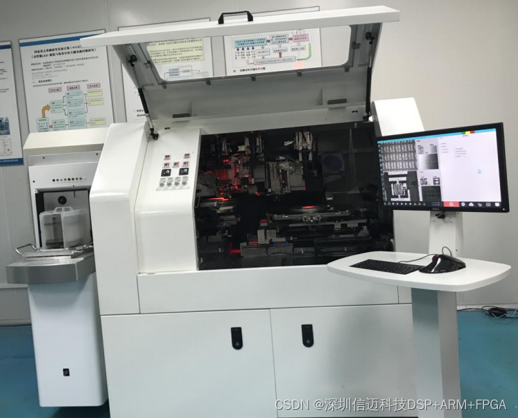
The wafer-level flip chip bonder is mainly composed of the wafer tray feeding module, wafer tray workbench module, flip chip module, bonding head module, substrate workbench module, dispensing module, vision module, and substrate loading/unloading module, as shown in Figure 2-2.
Wafer-Level Flip Chip Bonder Control System Architecture
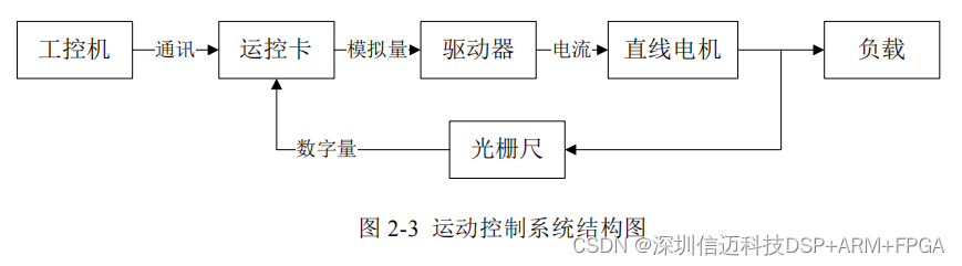
The motion control system of the wafer-level flip chip bonder is mainly composed of an industrial PC (IPC), motion control card, drivers, feedback devices, and a linear motor motion platform. The IPC serves as the host computer for the entire motion control system. The motion control card is directly plugged into the IPC's PCIe interface slot and allows for custom design of servo control algorithms. It controls the drivers by outputting analog DAC commands. The drivers are set to current loop control mode, amplifying and processing the input analog DAC commands to output corresponding current to the controlled object, thereby controlling the linear motor's reciprocating motion. The feedback device uses a Heidenhain incremental linear encoder. The positioning accuracy of the linear encoder determines the precision of the entire system, and its scanning frequency determines the theoretical maximum speed of the linear motor's motion. The basic motion control system architecture is shown in Figure 2-3.
Motion Control Card
A motion control card is a host computer control unit installed in a PCI or PCIe slot on an industrial PC. The core of the host computer control unit consists of high-speed DSP and FPGA chips, and it achieves coordinated control of multiple axes simultaneously by sending analog or pulse commands. The host computer for the wafer-level flip chip bonder control system uses the GHN series motion control card, newly developed by Googol Technology (Shenzhen), as shown in Figure 2-4.
The GHN is a network-based, modular plug-in motion control card. The main card communicates with the terminal board via the gLink-II bus in a serial manner. It uses a fifth-order PVT (Position-Velocity-Time) motion planner for basic motion planning. Its main features include a high-performance ADI SHARC processor (dual-core 32-bit floating-point DSP + ARM Cortex A5, main frequency 450MHz), support for multi-axis applications (up to 36 axes), and a control cycle of 250 µs. It also supports users downloading custom control algorithms to a DSP core for execution. Therefore, the GHN motion control card is suitable for self-developed high-speed, high-precision microelectronics packaging equipment.
Drive System
Since the servo algorithms for the entire control system are written on the motion control card, the drivers only operate in current loop mode. Their main function is to receive the analog DAC output from the motion control card, process it, and convert it into a proportionally corresponding current output to the controlled linear motor, serving an amplification role. Furthermore, when a three-phase AC direct-drive motor needs to find its phase angle during initialization, this is also accomplished by the driver. Therefore, neglecting the delay of the driver's internal electronic circuits, the driver model can be simplified to an amplification stage.
The main functions of the driver in the entire system are to complete the current loop, automatically find the phase angle when a three-phase motor is first powered on and enabled, receive command signals from the motion control card, and send alarm signals back to the motion control card. Other functions such as position, velocity, and current protection are also set within the driver.
Feedback Device
The feedback device is composed of a linear encoder and a read head. It is a measuring element that accurately feeds back the displacement signal of the motion platform to the motion control system in real time. It is mainly divided into two categories: absolute and incremental. Linear motors are generally paired with linear encoders, while rotary motors are paired with encoder disks, resolvers, or Hall sensors. The design requirements for the wafer-level flip chip bonder's motion platform specify positioning accuracy in the micrometer (µm) range, which requires the position measuring element to have high resolution. Since the controlled object requires high speed and high precision, the feedback device must have strong anti-interference capabilities. Considering the above factors, the measuring elements for the linear motion platform on the wafer-level flip chip bonder all use incremental linear encoders. Their positioning accuracy can reach 0.1µm, meeting or exceeding the positioning accuracy of similar products internationally.