AGV Mobile Robot and Autonomous Forklift Controller Design
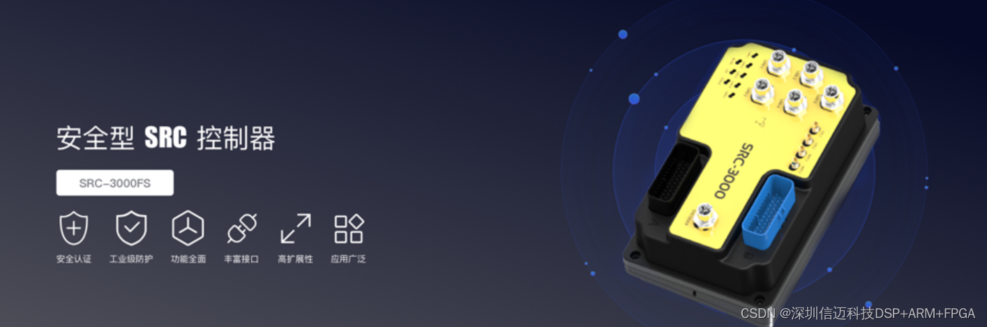
The AGV controller is a general-purpose controller designed for mobile robots (AMRs, smart forklifts, etc.), providing core functionalities such as map building, localization and navigation, and model editing for mobile robots. This solution integrates the core components of mobile robots into one unit, and with powerful client software, it helps users quickly set up robots. In addition, it has gradually evolved into a controller for smart factory infrastructure, capable of controlling automatic charging stations, automatic doors, elevators, traffic lights, and more. Under a unified scheduling interface framework, it drives the intelligent transformation and automation expansion of the entire factory.
The main control methods for AGV systems include centralized control, decentralized control, and distributed control.
Based on the principle of centralized control, the AGV system is designed with a three-layer architecture: the management and control layer, the transmission layer, and the execution layer. Each layer of the system is both independent and interconnected; while each layer completes specific tasks, it also serves other layers. The system's organizational structure is shown in Figure 2.1.
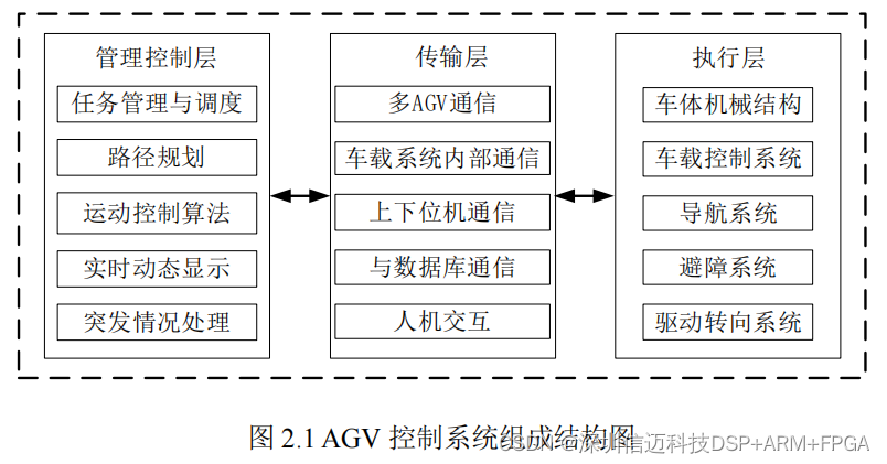
The management and control layer primarily refers to the ground control system, composed of system monitoring and management software, host PCs, and other components, serving as the brain of the entire AGV system. The transmission layer generally refers to communication between the ground control system and the on-board controller, but sometimes, depending on different system requirements, communication objects may be expanded and dedicated communication systems designed, acting as a robust bridge for task information transmission between systems. The execution layer is the main hardware component of the system, mainly including the vehicle body, guidance system, on-board control system, power system, drive and steering system, etc.
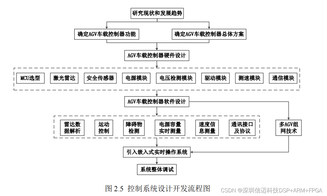
2 AGV On-board System Overall Design
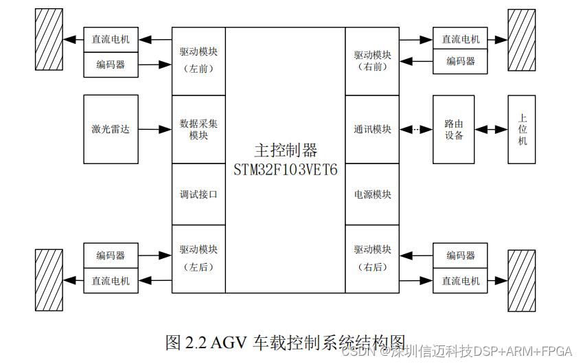
The on-board controller of an AGV system is a typical microcomputer control system centered around an Electronic Control Unit (ECU). The structure of the on-board control system is shown in Figure 2.2. As the execution layer of the AGV control system, the on-board control system controls vehicle actions by responding to commands issued by the management and control layer. Its main functions include system operation and motion control, vehicle status information acquisition, wireless communication, data interaction, and so on.
The AGV on-board control system mainly includes the on-board master controller module, lidar navigation module, DC motor drive module, power module, communication module, safety obstacle avoidance module, signal acquisition circuit module, and audio-visual alarm module. Among these, the on-board master controller module is the core of the AGV control system, responsible for controlling and coordinating other units of the AGV body to operate according to instructions. Its main tasks include signal input, processing and output, real-time control, fault diagnosis, and fault handling, to meet the real-time scheduling requirements of the AGV control system. The hardware modules of the on-board control system are connected via bus, with common connection methods including CAN, SPI, IIC, etc. [31]. Generally, AGVs use an MCU (microcontroller) as the control chip. Considering the complex industrial environment, which poses significant interference to control chips and systems, this research project uses STM32F103VET6 as the control core for the AGV, characterized by high stability and strong anti-interference capabilities.
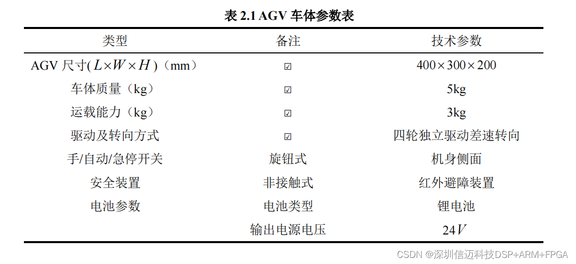
AGV Body Parameters
Since the AGV controller designed in this project is applied in a complex real-world operating environment, it requires corresponding software to control the controller to perform its normal functions, thereby ensuring the proper operation of the AGV. However, the on-board controller has numerous hardware modules, and consequently, multiple functions (applications) will run concurrently, such as radar data processing functions, AGV motion control functions, speed information acquisition functions, voltage and current data detection, and communication functions with the host computer. If the system were run in a single bare-metal mode (without any operating system), the following problems would arise: functions might constrain each other, and when one function executes, another might not get executed. Similarly, if a delay function is incorporated into an executable function, and the function is executing within that delay, other functions that need to run would not be executed. This would lead to system disarray, putting it in an uncontrollable state. This would cause extreme system instability, contrary to the performance requirements of the system design goals. Therefore, it is essential to introduce an embedded real-time operating system to manage these functions.
This paper selects RT-Thread as the operating system for the controller. The main reason for choosing this system as the real-time operating system is that the hardware system in this paper adopts an STM32 microcontroller architecture based on the ARM Cortex-M3 core. This architecture perfectly fits with the RT-Thread embedded real-time operating system. Additionally, as a free real-time operating system, it offers advantages in cost control. It also possesses many excellent features, such as the ability to manage 64 tasks, with applications supporting up to 256 tasks, ensuring good system operational stability and reliability [33].
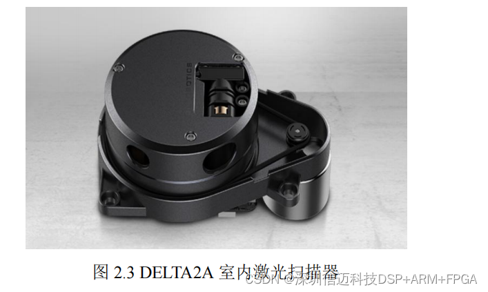
The positioning accuracy of laser guidance can reach millimeter level, and the reflective targets are small in size, mounted on walls, with minimal environmental impact. However, if the reflective targets are obstructed or too close to reflective objects, the positioning accuracy of the guidance system will be affected. Therefore, when installing reflective targets, their dimensions and the AGV's operating environment should be carefully considered. The Delta-2B lidar communicates with external devices via UART TTL levels. It only supports simplex communication (i.e., the lidar actively sends data frames to external devices). External devices only need to extract valid data from the data frames and do not need to send any response. All data in the communication frames are in hexadecimal format.
By parsing the communication data according to the communication protocol defined in this paper, real-time measurement information and device health status information can be extracted.
The communication frame consists of a frame header, frame length, frame type, command word, parameter length, parameters, and checksum. It is primarily used for the lidar to