FPGA+MPU+MCU-Based Fully Automatic Blood Cell Analyzer Solution
The fully automatic blood cell analyzer is one of the most widely used instruments in clinical laboratories at hospitals, employed for testing parameters such as red blood cells, hemoglobin, white blood cells, and platelets. As a fully automated intelligent device based on electronic and automation technologies, it offers comprehensive functionality and simple operation. With support from computer systems, it excels in data processing and analysis, enabling reliable multi-parameter analysis simultaneously. Through network connectivity and interactive touchscreens, it supports online information sharing and is extensively used in hospital clinical testing.
The hardware system of a fully automatic blood cell analyzer consists of three main lines. First is the data line, centered on an FPGA processor, primarily responsible for high-speed acquisition and collection of raw data. Second is the control line, based on an MCU processor, which mainly drives and controls peripheral components and detects sensor data. Third is the human-machine interaction line, led by an MPU processor, serving as the central controller for coordinating and managing modules, scheduling resources, processing data, visualizing results, and enabling human-machine interaction.
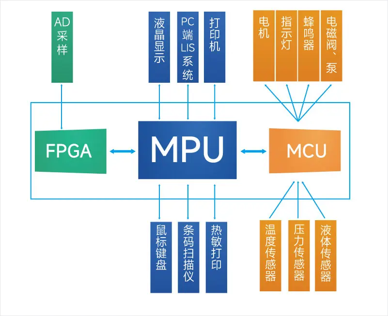
Hardware System of Fully Automatic Blood Cell Analyzer
The functional system of a fully automatic blood cell analyzer can be divided into the signal processing system, drive control system, and main control system. These major subsystems serve as the bridge connecting all components of the instrument and are directly linked with mechanical systems, software, and fluidics.
-
Signal Processing System: After capturing laser scattering signals, this system performs photoelectric conversion, followed by analog amplification and filtering—primarily eliminating noise—to condition the signal for AD conversion. The resulting digital signal is then sent to the FPGA for processing and storage.
-
Drive Control System: The drive control system includes three main functions: control, detection, and power driving. It receives commands from the main control system and generates drive logic signals according to predefined protocols. Detection provides feedback information for control purposes. Power driving converts logic signals into power-level signals to actuate power components.
-
Main Control System: As the core of the entire system, the main control system sends control commands via UART to the drive control system, where the MCU executes control operations for peripherals such as motors, solenoid valves, and pumps. Simultaneously, it sends data acquisition commands via SPI/PCIE to the FPGA in the signal processing system. After data acquisition and processing, the data is uploaded back to the main control system via SPI/PCIE for further processing and analysis. The analysis results are then displayed and printed through the touch display system, and transmitted over the network to hospital LIS or HIS systems.
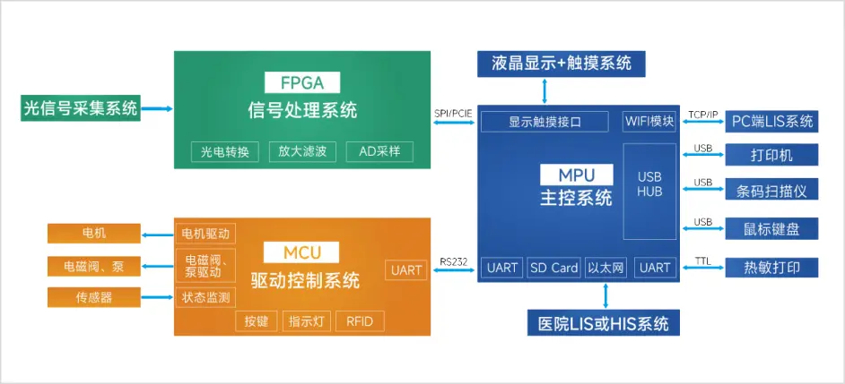
System Architecture Diagram of Fully Automatic Blood Cell Analyzer
The fully automatic blood cell analyzer solution integrates all three processor requirements—FPGA, MPU, and MCU—onto a single board. This three-chip integration significantly reduces hardware costs and design complexity for customers, while providing abundant development resources to accelerate product development.
-
Meets High-Speed Data Acquisition Requirements
Equipped with Xilinx Artix-7 FPGA resources comparable to Zynq 7010, it fulfills the high-speed data acquisition demands of the signal processing system. -
Superior Data Processing and Human-Machine Interaction Capabilities
The i.MX8M Mini's four Cortex-A53 cores deliver excellent data processing performance and support rich human-machine interfaces, meeting the main control system's requirements for data processing, task scheduling, and user interaction. -
Real-Time Detection and Control Functions
The i.MX8M Mini's single Cortex-M4 core provides real-time sensor data acquisition and control capabilities, satisfying the drive control system's need for real-time peripheral driving and data monitoring. -
High-Speed Communication Capability
The MPU and FPGA communicate via PCIe, achieving data transfer rates of 200–300 MB/s, ensuring fast and efficient data transmission.