Design and Testing of a Ground Surveillance Radar System
This article primarily introduces the composition and design of a ground surveillance radar system.
I. Functions and Performance Indicators
The XD-5000 ground surveillance radar is a small, one-dimensional phased array radar suitable for scenarios such as border surveillance, oil pipeline protection, and portable battlefield reconnaissance for individual soldiers. This radar features the following characteristics:
Wide Surveillance Range: Detection range for pedestrians ≥ 5 km, for vehicles ≥ 10 km, and azimuth coverage of 90°.
Strong Environmental Adaptability: The radar features online learning capabilities, allowing it to adapt to various environmental changes. Low Minimum Detectable Speed: Capable of detecting targets moving as slow as 0.3 m/s.
High Detection Accuracy: Range accuracy < 5 m, azimuth accuracy < 0.5°.
High Automation Level: Utilizes advanced TBD (Track Before Detect) algorithms, performing detection and tracking simultaneously, eliminating the need for manual operator tracking.
Target Classification and Recognition Capability: Employs AI pattern recognition algorithms to differentiate target types.
Small Size, Light Weight, Low Power Consumption: Adopting an integrated design concept, the radar weighs < 6 kg and consumes < 65 W, making deployment and retrieval convenient. Suitable for scenarios such as portable reconnaissance for individual soldiers and solar power supply.
High Reliability, Low Cost: The radar has no moving parts, significantly improving reliability compared to mechanically scanned radars. However, its cost is comparable to that of mechanically scanned radars.
The radar's technical specifications are as follows:
-
Detection Range (Pd≥0.9, Pfa<1e-9): ≥ 5 km (pedestrian, RCS=0.5 ㎡), ≥ 10 km (small vehicle, RCS=5 ㎡); ≥ 2.5 km (UAV, RCS=0.01 ㎡)
-
Frequency Band: Ku-band;
-
Azimuth Coverage: 90°;
-
Blind Zone: 50 meters;
-
Range Resolution: 10 meters;
-
Detection Accuracy: Range < 5m, Azimuth < 0.3°;
-
Minimum Detectable Speed: ≤ 0.3 m/s;
-
Maximum Trackable Target Speed: ≥ 60 m/s;
-
Number of Simultaneously Tracked Targets: > 100;
-
Weight: ≤ 6 kg;
-
Power Supply: 18~28VDC, Power Consumption < 65W;
II. System Composition
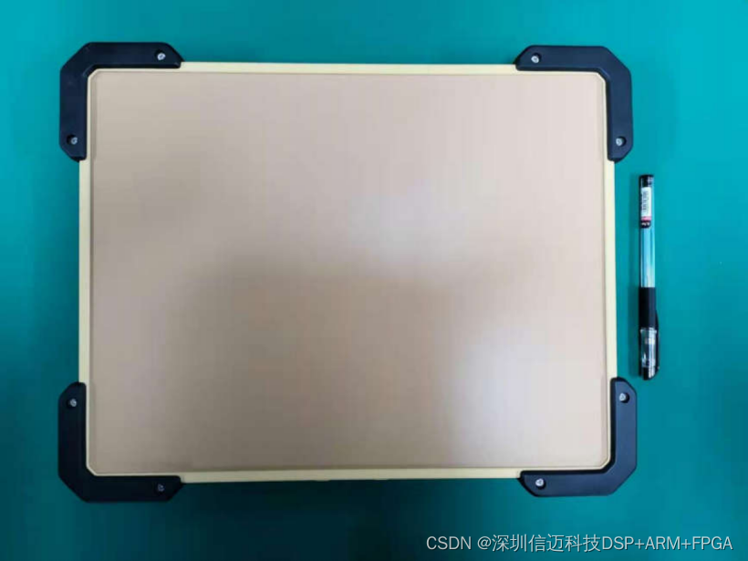
The system consists of the radar main unit, power adapter, accompanying cables, display and control terminal (optional), and accompanying mounting structure.
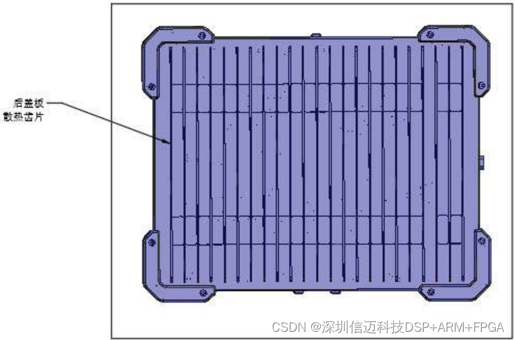
The radar main unit performs target detection, tracking, and information acquisition, and transmits target information to the display and control terminal via a Gigabit Ethernet port. The display and control terminal displays the target information output by the radar through a human-machine interface, and can also configure the radar's operating parameters. The power adapter is responsible for converting AC 220V to the DC voltage required by the radar. There are two accompanying cables in total: one for power supply and one for network communication. The accompanying mounting structure can be customized according to the customer's mounting platform, to meet installation requirements in various customer scenarios. The appearance of the radar main unit is shown in the figure:
System Composition Table:
Component Name | Quantity ---|--- Radar Main Unit | 1 Power Cable | 1 Network Communication Cable | 1 Power Adapter | 1 Display and Control Terminal (Optional) | 1 Accompanying Mounting Structure | 1
III. Workflow
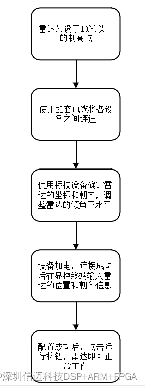
The radar is set up at a vantage point more than 10 meters above the ground, ensuring an unobstructed line of sight between the radar and the monitored area. Using calibration equipment, the radar setup is leveled, and the coordinates of the radar's installation location and its orientation are determined.
Connect the corresponding equipment to the radar using the accompanying cables. After the radar main unit is powered on, it automatically establishes a network connection with the display and control terminal. At this point, input the radar's coordinates and array orientation into the display and control software, click the 'Run' button, and the radar will operate normally, displaying the tracks and information of all moving targets within its field of view on the display interface.
The workflow is summarized as follows:
IV. Structure and Interfaces
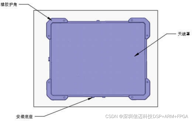
Main Unit Front View:
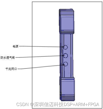
Side View:
Rear View:
The radar's power supply voltage is 18~28VDC, and the communication interface is a Gigabit Ethernet port. The power supply and communication interfaces are led out via two separate waterproof aviation connectors.
V. Product Partial Scenario Test Results
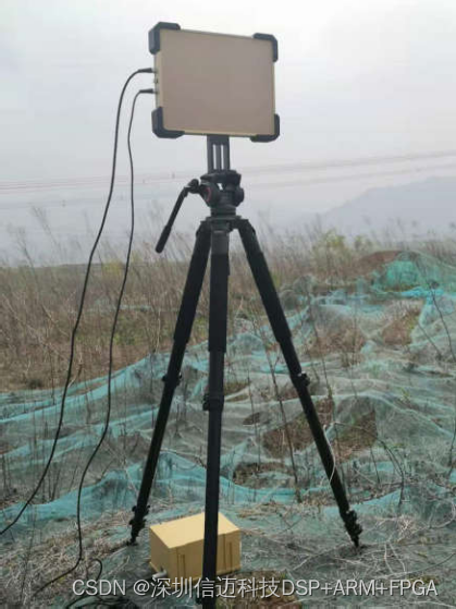
Field Test Photos
Partial Scenario Test Results
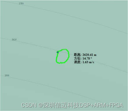
Human Target, performing circular motion with a 20m radius at 2.6 km
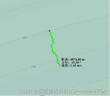
Human Target, walking in a field at 4.8 km
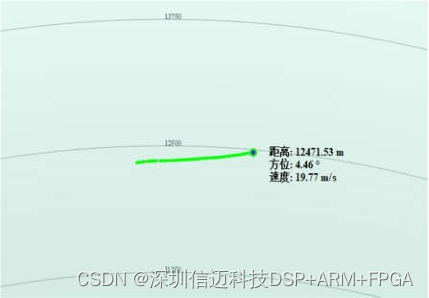
Vehicle Target on the Road