Introduction to DSP+ARM+FPGA High-Speed PCIe/Gigabit Ethernet Signal Simulation
First, a self-introduction. I am a Signal Integrity (SI) engineer, with 17 years of work experience to date. Of course, I haven't been exclusively working on signal integrity for all 17 years, but all my work has been related to it. I've done PCB layout, SIPI (Signal Integrity, Power Integrity) simulation, hardware design, testing, and other tasks, but the vast majority of my experience and effort has been focused on SIPI.
Naturally, when I first graduated, I wasn't doing SI. Thanks to a certain company's open technical platform, I, as a PCB layout engineer, was able to get exposed to SI. I believe many PCB layout engineers today, like me back then, are dissatisfied with the status quo and want to expand their skills, improve their compensation, and learn SI. However, they struggle with where to start, even though there are many signal integrity books available, making it overwhelming to choose from.
In a series of upcoming shares, I will introduce how I self-learned SI and became a signal integrity engineer, hoping to be helpful to PCB layout engineers who wish to learn SI. At the same time, I will try to comprehensively explain some SI theories, combining them with engineering applications, and share my insights from years of working in SI. My expertise is limited, so omissions are inevitable. I'm merely offering a humble opinion here, hoping to assist readers of my articles, and also hoping that experts can provide guidance to help me grow technically.
Enough small talk, let's get to the main topic. What is signal integrity?
Signal Integrity (SI), also commonly referred to as signal quality. As signal speeds increase, the transmission of digital signals can no longer solely consider logical implementation; it must also consider how to enable the receiving device to receive the correct signal waveform. It sounds simple: signal integrity is the study of how to ensure signals are transmitted correctly between a driver and a receiver. However, its scope is very broad and continuously expands into other disciplinary fields with the development of electronics and communication technologies. It not only includes circuit and transmission line theory but also involves electromagnetic field theory and has a close relationship with electromagnetic compatibility.
Signal integrity, as commonly understood, generally encompasses two aspects: one aspect studies signal transmission, focusing on how to optimize the signal's transmission path so that the receiving chip obtains the correct waveform; the other aspect studies power delivery, specifically how to provide a stable, low-noise power supply for stable chip operation, namely Power Integrity (Signal Integrity, PI).
Broadly speaking, signal integrity refers to all problems caused by interconnects in circuit design. It primarily studies how the electrical characteristic parameters of interconnects interact with the voltage and current waveforms of digital signals, thereby affecting product performance. This is mainly manifested in:
Timing: Deviations between clock and data signals prevent the clock from correctly sampling the signals; Electromagnetic radiation, electromagnetic interference, and other external disturbances cause the circuit board to malfunction; Loss and Attenuation: The signal transmission channel experiences loss, and by the time it reaches the receiver, it has attenuated below the receiving chip's threshold; Switching Noise: Simultaneous switching of multiple signal lines causes ground bounce and power bounce, reducing signal noise and timing margins; Crosstalk: Improper routing leads to interference between adjacent signals; Signal Ringing and Overshoot: Impedance mismatch or excessive driving strength causes overshoot and ringing on the received signal; Non-monotonic Edges: Non-monotonicity of clock signal edges prevents the clock from correctly sampling data. ......... Signal Integrity analysis applies traditional theories from circuit, transmission line, electromagnetics, signals and systems, and other disciplines to solve the interconnect-related problems in circuit design mentioned above.
To put it more plainly, signal integrity is the study of how to ensure that signals emitted by a driver chip are correctly received by a receiver chip after passing through a transmission channel.
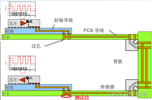
From this straightforward description, it's easy to see that signal integrity comprises three key elements:
Signal: The entity being transmitted. We must first understand and be familiar with its characteristics. Chips: Divided into driver chips and receiver chips. A signal integrity engineer's goal is to achieve correct signal transmission between these driver and receiver chips. Transmission Channel: The medium