Ximea's Technical Approach and Application Scenarios for 3D Machine Vision
1. Typical Application Areas of 3D Cameras:
-
Obstacle detection and "human-like" navigation for autonomous vehicles (e.g., forklifts) in industrial environments
-
Robot control for pick-and-place operations on conveyors or part handling tasks
-
Presence/absence inspection and counting of objects within containers or boxes, even when objects exhibit no contrast against the background
-
Position and presence verification of components on circuit boards
-
Volume measurement of various objects, etc.
2. Popular 3D Technologies
Commonly used techniques in 3D image processing include:
-
Stereo vision and structured light
-
Laser triangulation
-
ToF (Time-of-Flight)
3. Stereo Vision and Structured Light
Stereo vision operates on the same principle as human binocular vision. Two 2D images of an object are captured using two cameras. The same scene is recorded from two different positions, and using triangulation, a 3D image incorporating depth information is synthesized.
Stereo vision uses image data from two standard 2D area-scan cameras to generate depth values for a scene. The images are rectified based on the camera positions and geometric information of the application. After rectification, matching algorithms search for corresponding points in the left and right images to create a depth map of the scene.
The working distance of this method depends on the baseline (distance between the cameras), and thus varies depending on the setup.
One way to enhance the performance of a stereo system is to add structured light. By projecting bright geometric patterns onto the scene using a light source, measurement accuracy can be significantly improved, effectively reducing stereo imaging defects caused by homogeneous surfaces and low lighting. With proper calibration of the projector and camera, it is even possible to eliminate the need for a second camera.
3.1 Advantages and Disadvantages of Stereo Vision
+ High accuracy achievable at short distances
+ Can use standard 2D area-scan cameras
+ Not affected by sunlight
+ Works well on highly reflective (so-called "challenging") surfaces
- Not suitable for homogeneous surfaces
- Cannot operate under low-light conditions
- High computational load makes real-time operation difficult
3.2 Advantages and Disadvantages of Structured Light
+ High accuracy achievable at short distances
+ Can use standard 2D area-scan cameras
+ Not affected by sunlight
+ Works well on highly reflective (challenging) surfaces
- High computational load makes real-time operation difficult
- Complex setup and high installation cost lead to high overall system cost
3.3 Typical Application Areas of Stereo Vision and Structured Light
Stereo vision enables high measurement accuracy. Challenging surfaces do not significantly affect stereo vision, but the method always requires the object to have some reference markers or random texture. This makes the technology generally less suitable for use in production environments. Typical applications of stereo vision include coordinate metrology, 3D measurement of objects and workspaces in industrial, service, or robotic systems, and 3D visualization of hazardous or inaccessible areas. Stereo systems are also well-suited for outdoor measurement applications, such as measuring and inspecting logs in sawmills.
However, if high processing load, complex installation, and higher cost are acceptable, adding structured light makes stereo vision suitable for industrial target measurement applications.
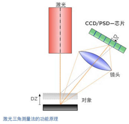
4. Laser Triangulation
Laser triangulation combines a 2D camera with a laser light source. In this process, a laser projects a line or point onto the scene in front of the camera.
The laser line or point appears on the object and is captured by the 2D camera. When the camera moves across or alongside the target (e.g., via a conveyor belt), the distance between the object and the sensor changes, causing the observation angle of the laser line or point—and thus its position in the camera image—to shift. Using mathematical calculations, the distance between the object and the light source can be determined from the position coordinates in the image.
4.1 Advantages and Disadvantages of Laser Triangulation
+ Extremely high accuracy
+ Operates well under poor lighting conditions
+ Suitable for specular or highly reflective (challenging) surfaces
- Requires laser scanning, resulting in slower speed
- Limited working distance
- High accuracy demands very expensive individual components
- Complex setup and high installation cost lead to high overall system cost
- Eye safety cannot be guaranteed without proper safety measures
4.2 Application Areas of Laser Scanners
Laser triangulation is often an excellent choice for applications requiring high accuracy. It is also recommended for challenging surfaces with high reflectivity and poor lighting conditions. For example, measuring highly reflective metal sheets at sub-millimeter precision is a typical application. Another example is glass bottle sorting, where contrast is minimal.
5. Time-of-Flight Method
The Time-of-Flight method is a highly efficient technique for acquiring depth data and measuring distance. A ToF (Time-of-Flight) camera provides two types of information for each pixel: brightness value (represented as grayscale) and the distance between the camera and the target (i.e., depth value).
There are two different implementations of the ToF (Time-of-Flight) method: continuous-wave and pulsed ToF. Continuous-wave ToF measures distance based on the phase difference between emitted and reflected light from a modulated light source.
Cameras using the pulsed ToF principle determine distance based on the time delay between the emitted and reflected light pulses.
A ToF (Time-of-Flight) camera is a compact system with no moving parts, consisting of the following components:
- Integrated active light source
- Integrated lens
- ToF (Time-of-Flight) sensor chip
The light source emits light pulses, which reflect off objects and return to the camera sensor. The integrated lens ensures the reflected light reaches the sensor. In simple terms, the distance is determined by measuring the time it takes for light to travel from the source to the object and back to the sensor. This enables straightforward, real-time generation of point clouds/depth maps, along with intensity and confidence maps.
5.1 Advantages and Disadvantages of ToF
+ Captures entire scene in a single shot—no scanning required
+ High speed
+ Provides both 2D and 3D information in a single image
+ High X/Y resolution
+ Compact system with no moving parts
+ Ideal performance under low-light conditions
+ Eye-safe
+ No requirement for texture or contrast
+ Long working distances possible with sufficiently powerful illumination
+ Low overall system cost
+ Enables high real-time performance
- Struggles with specular reflections and highly reflective (challenging) surfaces
- Sensitive to ambient light interference
5.2 Typical Application Areas of ToF (Time-of-Flight)
ToF cameras are suitable for applications requiring long working distances, high-speed imaging, and low system complexity. If these advantages are desired, budget is limited, and sub-millimeter accuracy is not required, ToF technology is an ideal choice.
Volume measurement for logistics, palletizing, and depalletizing tasks, as well as autonomous vehicles in logistics environments, are well-suited for ToF (Time-of-Flight) cameras. ToF (Time-of-Flight) cameras are also finding exciting new applications in the medical field, such as patient positioning and monitoring. In industrial applications, due to their relatively lower depth accuracy, ToF-based systems are better suited for general tasks such as selection and placement of large objects. They can also be used in robotic control systems or for measurement and position detection of large objects, such as in automotive manufacturing.
6. Comparison of 3D Technologies
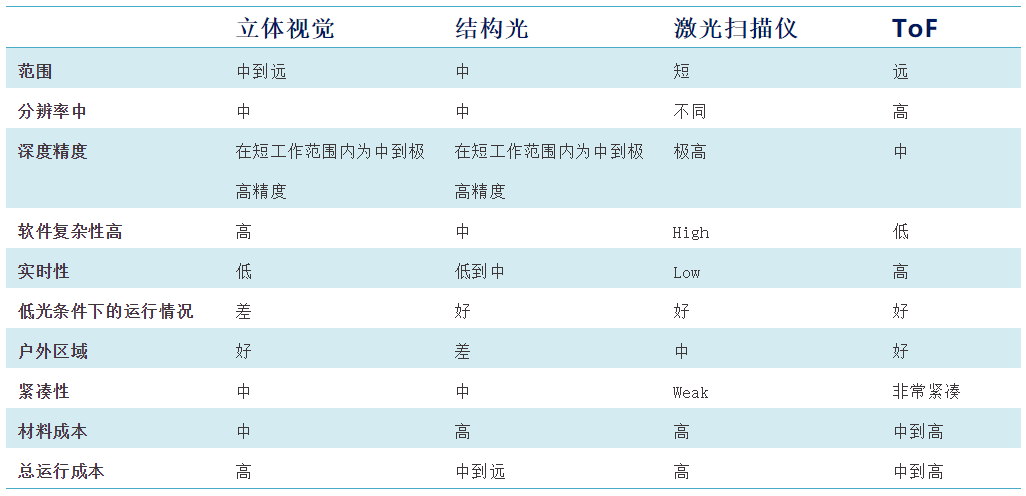
Source from: Martin Gramatke of Basler