ZYNQ-based Mobile Robot Controller Design (2) Design Approach
The mobile robot solution proposed in this paper aims to contribute to solving the aforementioned problems. This solution is suitable for the following application scenario: the robot relies on a simple, robust mechanical structure with sufficient strength to protect the control board and associated circuits, serving as a carrying platform. Movement is achieved by motor-driven wheels, operating in indoor and outdoor environments with non-adverse ground conditions, at low to medium speeds. The robot carries various common sensors, such as ultrasonic, infrared, laser, gyroscope, encoder, camera, etc., for environmental perception and self-pose estimation, and uses these sensors to achieve autonomous or human-intervened obstacle avoidance, map creation, path planning, image processing, and recognition functions.
To make this application scenario more concrete and tangible, the following scenario was artificially set during the experimental process of this paper: the robot carries a relatively large number of ultrasonic sensors (8-16 channels) and one camera, operating in indoor and outdoor environments around the B3 laboratory, at a low speed, with a maximum speed less than 100cm/s, and can return real-time surrounding views via a network camera. The robot has two movement modes: roaming and manual control. In roaming mode, the robot can perform autonomous obstacle avoidance; in manual control mode, the robot receives and executes movement commands sent from the console. The operator can access the robot control interface via a browser, monitor the current sensor status, and manually send control commands. The operator can interrupt and resume the robot's roaming state at any time.
2 Overall Framework Design of the Mobile Robot Controller
This section provides an overall analysis and presentation of the mobile robot controller's overall framework proposed in this paper. We adopt the classic hierarchical paradigm of robotics to divide the system into three layers: Drive and Sensing Layer, Real-time Control Layer, and Interaction Layer. The overall framework is shown in Figure 2-1:
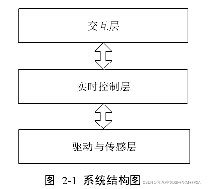
The Drive and Sensing Layer acts as the "eyes" and "legs," responsible for scheduling the multiple heterogeneous sensors carried by the robot (up to 16 channels of ultrasonic sensors and a camera in this paper), preprocessing the environmental information captured by the sensors, and simultaneously providing power drive for the mobile robot. The Real-time Control Layer manages various real-time tasks of the robot control system, such as action decision-making, command execution, emergency stops, and various other interruptions. The Interaction Layer manages information exchange between the external world and the robot system. The console interface runs on this layer, allowing access via the network to view the robot's current status and manually issue control commands. Next, we will analyze and elaborate on each layer separately.
2.2.1 Drive and Sensing Layer
The Drive and Sensing Layer is responsible for power drive and environmental information. This part is responsible for triggering and scheduling various heterogeneous sensors, preprocessing multi-channel sensor information, including data fusion and data forwarding, as well as motor driving. This subsection introduces the structural hierarchy of the Drive and Sensing Layer.
This layer is primarily used for acquiring and preprocessing sensor information, as well as motor driving. Its constituent modules are shown in Figure 2-2:
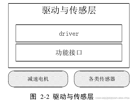
Currently, there is a wide variety of mainstream sensors on the market. Common ones include: ultrasonic sensors, infrared sensors, laser sensors, Hall sensors, photoelectric sensors, image sensors, accelerometers, gyroscopes, etc. Many of these are mature modules, and the range of precision selection is quite flexible for different needs. When rapidly building a mobile robot system, developers might consider using these sensor modules, which can reduce the time spent on designing individual sensor circuits and allow them to focus on implementing robot functionalities. This paper primarily uses two types of sensors: ultrasonic (8-16 channels) and a network camera. The hardware interface types for sensors are also very diverse. In this paper, we select common interfaces, whose types are basically covered by the following categories: GPIO type, IIC type, SPI type, RS232/485 type, USB type, as well as PWM, CAP type, bus type, etc. This paper mainly involves GPIO, USB, bus type, and EMIO type. Among them, the EMIO interface is a proprietary type for Xilinx Zynq platforms, which will be specifically introduced in Chapter 3 of this paper. 2.2.2 Real-time Control Layer The Real-time Control Layer is the core of the robot control system. It connects downwards to the Drive and Sensing Layer, making environmental judgments based on currently captured sensor information, calculating the actions the robot should take at that moment via a decision module, and issuing action commands through its interface with the Drive and Sensing Layer. It connects upwards to the Interaction Layer, providing feedback on the robot's current status to the console through its interface, while also receiving operator commands from the console and using these commands to interrupt the robot's current state. The Real-time Control Layer is the most critical part of the robot controller system presented in this paper. Figure 2-3 shows the functional modules of the Real-time Control Layer:
The key technologies of the Real-time Control Layer mainly lie in the following areas: (1) Interface implementation with the other two layers: the Drive and Sensing Layer, and the Interaction Layer. This includes the setting of communication interfaces and the implementation of communication protocols between different layers, primarily achieved through shared memory, which will be detailed in Chapters 4 and 5 of this paper. (2) Algorithm design for the decision module, which is responsible for processing a large amount of real-time data. The robot's action decisions are implemented in a state-machine-like manner. This will be detailed in Chapter 5 of this paper. (3) Interrupt mechanism configuration. In the scheme adopted in this paper, we will build an interrupt IP core in the FPGA to achieve hardware-software co-design for the interrupt module.
2.2.3 Interaction Layer
The Interaction Layer provides services for the mobile robot's non-real-time task requirements, human-machine interaction, and high-performance task processing. Theoretically, this layer supports operators interacting with the mobile robot via other terminals such as PCs, smartphones, tablets, and other devices. It is the top layer among the three layers of the mobile robot control system, connecting downwards to the Real-time Control Layer and communicating with it through a dedicated interface. In this paper, this layer serves two purposes: First, monitoring, which means it can monitor the robot's current state, including its own status and the surrounding environment's status; Second, commanding, which means at any time required by the operator, it can manually interrupt the robot's current state and issue appropriate commands.
Figure 2-4 shows a simplified structural diagram of the Interaction Layer:
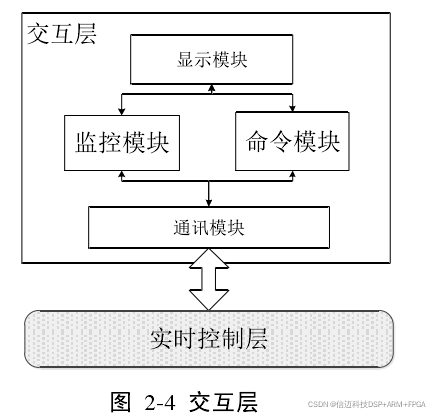
This layer mainly consists of the following key modules: (1) Communication module: This module is responsible for implementing the communication interface with the Real-time Control Layer. In this paper, it is implemented through shared memory, which will be detailed in Chapter 5 of the paper. (2) Monitoring module: A module used to reflect the mobile robot's surrounding environment or its own current state. (3) Command module: Allows operators to issue commands to the mobile robot through this module. (4) Display submodule: A submodule existing for convenient human-machine interaction, transmitting information to the outside world via displays and other devices.