Architecture of a High-Speed Data Processing Board Based on C66x and Domestic FPGA
Table of Contents
Overview
C66x Processor Core
C66x Pipeline Structure
Overview
The C66x DSP is the latest generation of fixed-point and floating-point DSPs, comprising four multipliers to perform single-precision floating-point operations. The C66x DSP core can simultaneously execute up to eight floating-point multiplication operations, and coupled with a clock frequency of up to 1.4GHz, it achieves high floating-point processing performance. By integrating multiple C66x DSP cores with other cores, high-performance multi-core System-on-Chip (SoC) devices can be created. This article uses the TMS320C6678 as an example to introduce the C66x core.
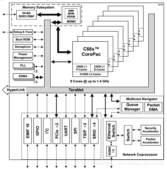
The TMS320C6678 features eight C66x cores, with each core operating at a maximum frequency of 1.4GHz, theoretically achieving processing performance of 179.2 (22.4x8) GFLOPs and 358.4 (44.8x8) GMACs. Each processor contains multi-level memory: L1P, L1D, and L2SRAM within the C66x core; and MSM SRAM as shared memory for multiple cores. The processor includes several multi-core shared external resources such as a Multicore Navigator, Network Coprocessor, Packet Accelerator, Semaphores, and PLL, while also providing various external interfaces like SRIO, PCIe, and EMIF. The processor architecture of the C6678 is shown in the figure below:
C66x Processor Core
The C66x core is the heart of the C6678 processor, designed to accomplish high-performance processing tasks.
The C66x core consists of the following components: C66x DSP, Level 1 Program Memory Controller (L1P), Level 1 Data Memory Controller (L1D), Level 2 Memory Controller (L2), External Memory Controller (EMC), eXtended Memory Controller (XMC), Bandwidth Manager (BWM), Interrupt Controller, and Power Down Controller (PDC). The core structure is as follows:
The C66x DSP comprises 8 functional units, 2 register files, and 2 data paths, with its structure shown in the figure below. The two register files contain a total of 64 registers, divided into two groups, A and B, each consisting of 32 32-bit registers. General-purpose registers can be used to store data or serve as address pointers. Supported data types include 8-bit packed data, 16-bit packed data, 32-bit data, 40-bit data, and 64-bit data, with multiplication supporting 128-bit data.
The 8 functional units (.L1 .S1 .M1 .D1 .L2 .S2 .D2 .S2) can each execute one instruction per clock cycle. .S units perform typical shift, branch, and comparison operations, while .L units execute common arithmetic and logical operations; all multiplication instructions are executed in the .M units (one .M unit contains 16 sets of 16x16-bit multipliers, capable of executing one single-precision floating-point multiplication operation per cycle, and one double-precision floating-point multiplication operation every four cycles). .D units primarily handle loading data from memory to the register file and storing results from the register file back to memory.
C66x Pipeline Structure
Computer pipelining was first introduced by Intel in the 486 chip. In a CPU, instruction execution is divided into several distinct functional units. A pipeline for instruction processing is formed by multiple circuit units with different functions. An x86 instruction is then broken down into several steps, which are executed by these respective circuit units. This approach allows for the completion of one instruction per CPU clock cycle, thereby increasing the CPU's operational speed.
The C66x DSP's pipeline structure is divided into three stages: Instruction Fetch, Instruction Decode, and Instruction Execute. The detailed pipeline structure for each stage is as follows:
Stage Pipeline Name Meaning
Fetch PG Program address generate: Generates the program address
PS Program address send: Sends the program address
PW Program (memory) access ready wait: Waits for program memory response
PR Program fetch packet receive: Receives the instruction packet returned from memory
Decode DP Instruction dispatch: Dispatches instructions to the corresponding functional units
DC Instruction decode: Decodes instructions within the corresponding functional units
Execute E1 Execute instruction; different instructions have different execution pipeline operations
...
E5
Illustration of Fetch stage pipeline operations:
Illustration of Decode stage pipeline operations:
Illustration of Execute stage pipeline operations: