Design and Implementation of a Sound Source Localization System Based on the OMAP Platform
The primary objective of a sound source localization system is to determine the spatial position information of a sound source. Currently, most research achievements in sound source localization systems focus on sound source localization algorithms, with relatively less work on embedded system design and implementation. Therefore, this paper designs a sound source localization system based on the OMAP platform, utilizing sound source localization algorithms to achieve sound source localization on the system.
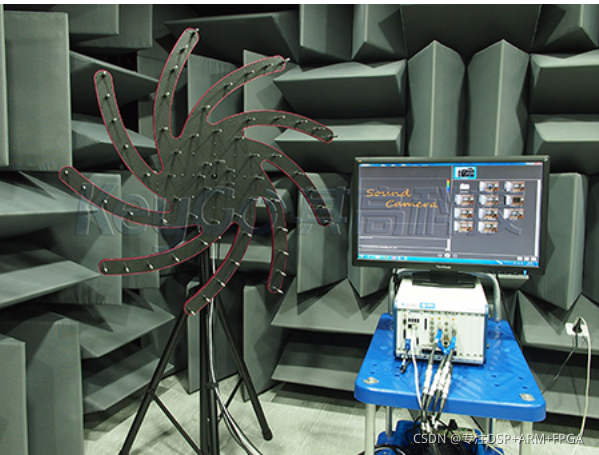
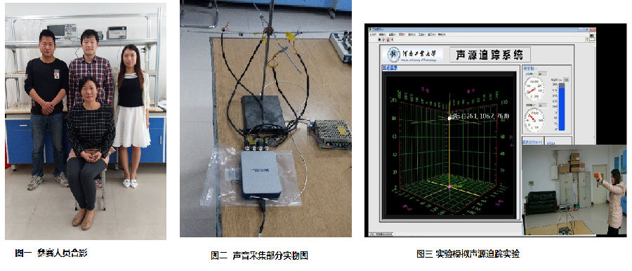
This paper first analyzes and compares three main methods for sound source localization based on microphone arrays, focusing on four primary algorithms for sound source localization based on time delay estimation. It then uses Matlab to simulate the Generalized Cross-Correlation (GCC) function algorithm for a planar four-element cross array. Next, this paper designs and implements the hardware and software for the sound source localization system based on the OMAP platform. The design uses an FPGA+OMAPL138 (with embedded ARM+DSP dual-core) as the core processor for the acquisition system. The precise timing logic characteristics of the FPGA are utilized to control the AD module, achieving accurate synchronous acquisition of four-channel audio signals. The powerful data processing capability of the DSP (C6748) within the OMAPL138 is used to perform complex algorithmic computations on the acquired audio signals. The rich peripheral interfaces of the ARM9 core within the OMAPL138 and its portable embedded Linux operating system are used to control the operation of the entire acquisition system, handle result processing, and other functions. For the hardware part, Cadence 16.3 software was used for schematic design and PCB design. The software part adopts a modular programming approach. On the FPGA side, Verilog programming is used to implement the AD module's acquisition function. On the OMAP side, the main tasks include Linux system porting, root file system creation, wireless network card driver porting, and uPP interface (for OMAPL138-FPGA communication) driver porting.
1 Evaluation Board Introduction Based on TI OMAP-L138 (fixed-point/floating-point DSP C674x + ARM9) + Xilinx Spartan-6 FPGA processor; OMAP-L138 and FPGA are connected via uPP, EMIFA, and I2C buses, with communication speeds up to 228 MByte/s; the OMAP-L138 has a main frequency of 456MHz, offering computing power up to 3648 MIPS and 2746 MFLOPS; FPGA is compatible with Xilinx Spartan-6 XC6SLX9/16/25/45, providing strong platform upgrade capability; The development board exposes rich peripherals, including high-speed data transfer interfaces such as Gigabit Ethernet, SATA, EMIFA, uPP, USB 2.0, as well as common interfaces like GPIO, I2C, RS232, PWM, and McBSP; Certified through high and low-temperature tests, suitable for various harsh working environments; DSP+ARM+FPGA triple-core SOM, with dimensions of 66mm*38.6mm, using industrial-grade B2B connectors to ensure signal integrity; Ø Supports bare-metal, SYS/BIOS operating system, and Linux operating system.
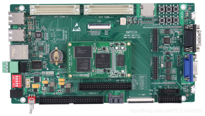 Figure 1 Front and Side Views of the Development Board
The XM138F-IDK-V3.0 is a development board designed by Shenzhen Xinmai based on the XM138-SP6-SOM System-on-Module (SOM), featuring a 4-layer board design with immersion gold and lead-free process. It provides users with a test platform for the XM138-SP6-SOM SOM, enabling rapid evaluation of its overall performance.
The XM138-SP6-SOM exposes all CPU resource signal pins, making secondary development extremely easy. Customers only need to focus on upper-layer applications, significantly reducing development difficulty and time costs, allowing products to be launched quickly and seize market opportunities in a timely manner. It not only provides rich demo programs but also detailed development tutorials and comprehensive technical support to assist customers with baseboard design, debugging, and software development.
2 Typical Application Areas Data Acquisition, Processing, and Display Systems Smart Power Systems Image Processing Equipment High-Precision Instrumentation Mid-to-High-End CNC Systems Communication Equipment Audio and Video Data Processing
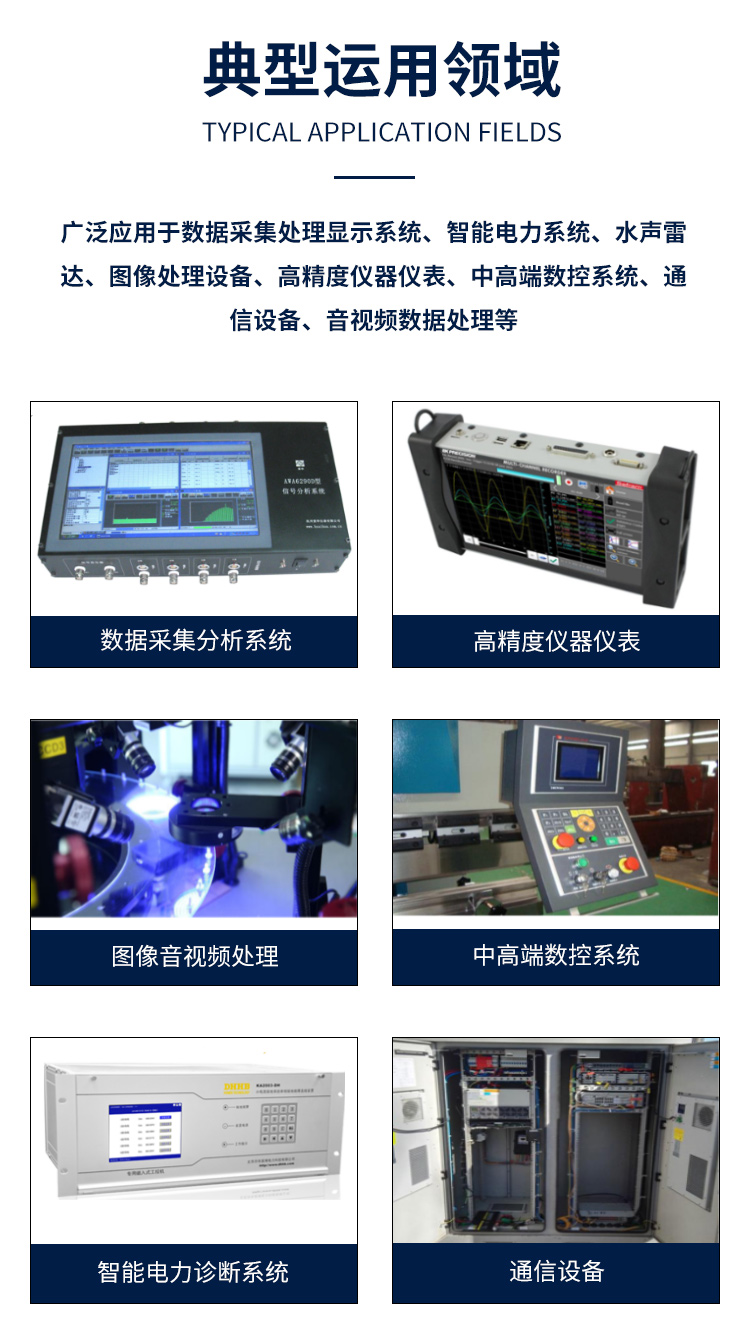 Figure 2 Typical Application Areas
3 Hardware and Software Parameters
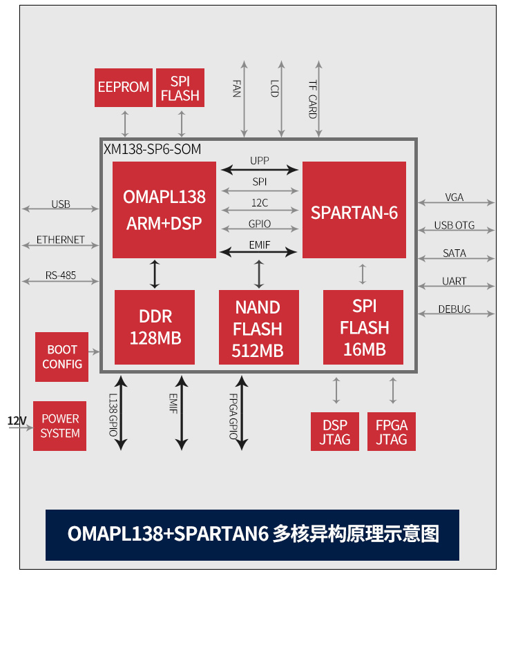 Schematic Diagram of Development Board Peripheral Resources Block Diagram
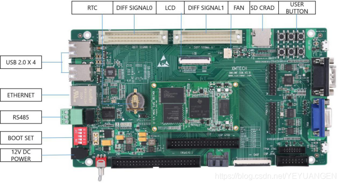
Figure 3 Development Board Interface Diagram
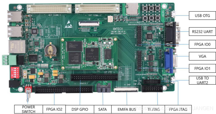
Figure 4 Development Board Interface Diagram