基于AM5728的PROFIBUS 通信测试
Title: PROFIBUS Communication Testing Based on AM5728
Content:
PROFIBUS Communication Testing
Ø 1. Hardware Connection
Connect the debug serial ports of two XM5728-IDK-V3 development boards to the PC using Micro USB cables, and open the serial debugging windows. Use jumper wires to connect the PROFIBUS interfaces of the two XM5728-IDK-V3 boards: connect A to A, B to B, and GND to GND. Ensure the terminal blocks are removed before connecting, as poor terminal contact previously caused signal transmission issues. For hot-plug testing, cut one wire (e.g., the A wire) in the middle and manually connect/disconnect it instead of doing so at the terminal blocks (which may cause problems). Wire connection inspection is critical.
Insert the prepared master/slave SD boot cards into the respective SD card slots of the XM5728-IDK-V3 boards. Power both boards using 12V-2A DC power supplies.
Ø 2. Communication Testing
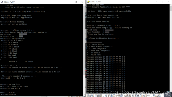
First, power on the XM5728-IDK-V3 board configured as the slave device. No additional configuration is required for the slave device during this test—it will wait for the master device to connect after booting. The following output can be observed in the serial debugging window:
After starting the slave device, power on the XM5728-IDK-V3 board configured as the master. Open the serial debugging window, where the following information will be printed:
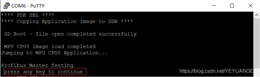
Figure 131
When the prompt "press any key to continue" appears, quickly press Enter to proceed with configuration. If no key is pressed within the timeout period, the system will skip configuration, requiring a restart of the master device. The following steps involve configuring the communication baud rate, slave number, and slave address.
Configure the communication baud rate, which must not exceed 500K. Select the desired baud rate from the options—for this test, choose 500K by entering the corresponding number 4, as shown below:
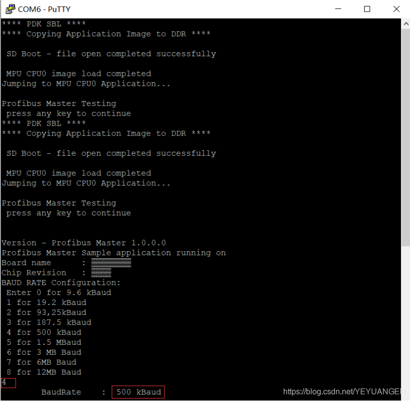
Figure 132
For this test, set the slave number to 1 and the slave address to 4, as shown below:
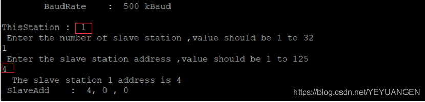
Figure 133
After configuration, the master device's serial debugging window will display the following output:
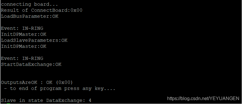
Figure 134
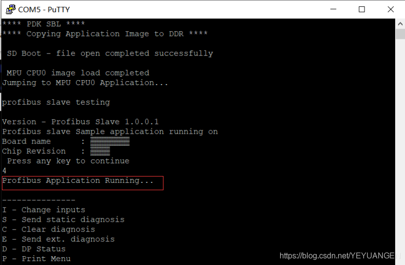
Once configured, switch to the slave device's serial debugging window, where continuous data printing indicates successful reception of data from the master device:
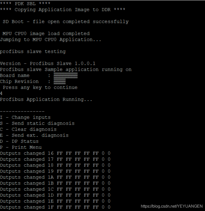
Figure 135
27.3
Hot-Plug Testing
The PROFIBUS interface supports hot-plugging. If communication is ongoing between the two boards, disconnecting the PROFIBUS interface will cause the master device's serial port to print:
Slave out of state DataExchange: 4
Simultaneously, the slave device will stop receiving data and printing information. Reconnecting the PROFIBUS interface will restore communication, with the master device printing:
Slave in state DataExchange: 4
The slave device will resume data reception and printing. The master device's serial output is shown below:
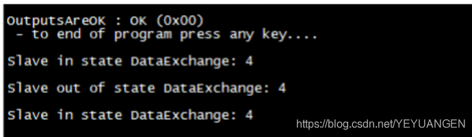
Figure 136
Profibus test: