Online Monitoring System for Power Parallel Capacitor Equipment Based on OMAPL138 DSP+ARM
Parallel capacitor equipment is a widely used reactive power compensation device in power transmission and distribution systems, effectively improving system power factor and increasing equipment utilization. However, high-voltage parallel capacitors operate under full load with large rated currents, making them prone to aging of capacitor elements after prolonged operation, which can lead to capacitor damage and significant changes in capacitance values. This article aims to develop an online monitoring system for capacitor equipment that effectively monitors the operational status of power capacitors and enables analysis and localization of fault causes when failures occur.
The principle of the online monitoring system involves conditioning AC voltage and current signals, which are then connected to an A/D sampling board for isochronous sampling. The sampled sequences are synchronized using a shift linear interpolation algorithm. Subsequently, FFT algorithms from digital signal processing are applied for harmonic analysis, extracting RMS values of fundamental voltage and current signals. Based on these values, the real-time capacitance of the capacitor is calculated. By applying a capacitance fault criterion algorithm, the system can accurately determine whether a capacitor fault has occurred.
The control system employs TI's OMAP-L138 processor, which integrates an ARM9 processor core and a C6748 DSP core. The C6748 core supports floating-point operations and offers strong computational performance. The ARM9 core provides high flexibility for developers and, when combined with an embedded Linux operating system, enables convenient file system management and task scheduling. The Qt-based graphical user interface ensures intuitive status display and user-friendly human-machine interaction.
Although the monitoring system requires further field testing and validation, laboratory tests have demonstrated that basic electrical parameter measurements already meet the requirements for online monitoring.
1 Evaluation Board Overview
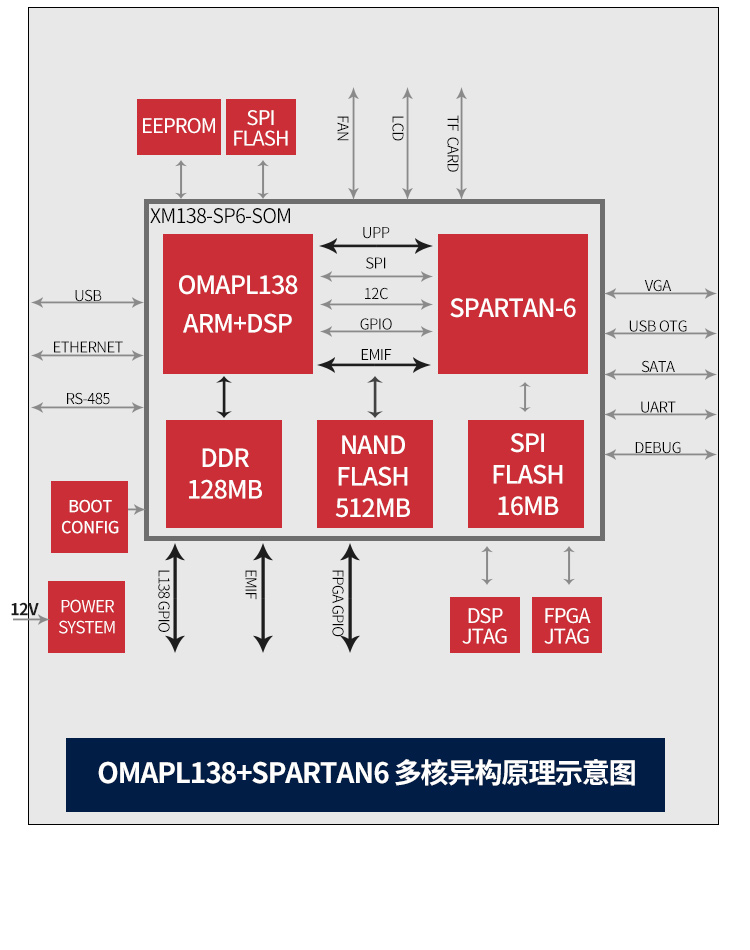
Based on TI OMAP-L138 (fixed/floating-point DSP C674x + ARM9) + Xilinx Spartan-6 FPGA processor;
OMAP-L138 connects to FPGA via uPP, EMIFA, and I2C buses, supporting communication speeds up to 228 MByte/s;
OMAP-L138 runs at 456 MHz, delivering up to 3648 MIPS and 2746 MFLOPS computational performance;
FPGA compatible with Xilinx Spartan-6 XC6SLX9/16/25/45, offering strong platform upgrade capability;
DSP + ARM + FPGA tri-core SOM (System-on-Module), sized 66mm × 38.6mm, uses industrial-grade B2B connectors to ensure signal integrity;
Supports bare-metal, SYS/BIOS, and Linux operating systems.
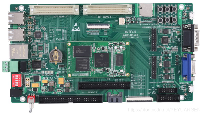
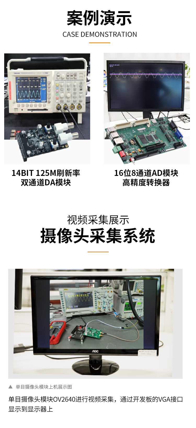
Figure 1 Front and side views of the development board
The XM138F-IDK-V3.0 is a development board designed based on Shenzhen Xinmeng's XM138-SP6-SOM core module. It features a 4-layer PCB design with lead-free immersion gold finish, providing a testing platform for the XM138-SP6-SOM core module, enabling rapid evaluation of its overall performance.
The XM138-SP6-SOM exposes all CPU resource signal pins, making secondary development extremely easy. Customers can focus solely on application-level development, significantly reducing development difficulty and time-to-market, enabling faster product launches and timely market capture. In addition to providing rich demo programs, detailed development tutorials and comprehensive technical support are also offered to assist customers with baseboard design, debugging, and software development.
2 Typical Application Areas
Data acquisition, processing, and display systems
Smart power systems
Image processing equipment
High-precision instruments and meters
Mid-to-high-end CNC systems
Communication equipment
Audio and video data processing
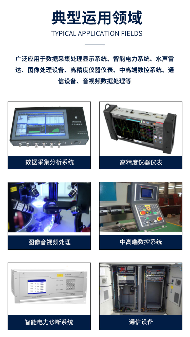
Figure 2 Typical application areas
3 Hardware and Software Specifications
Peripheral resource block diagram of the development board
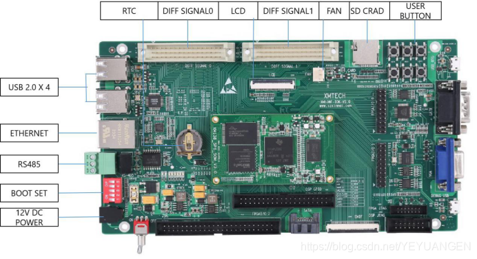
Figure 3 Development board interface diagram
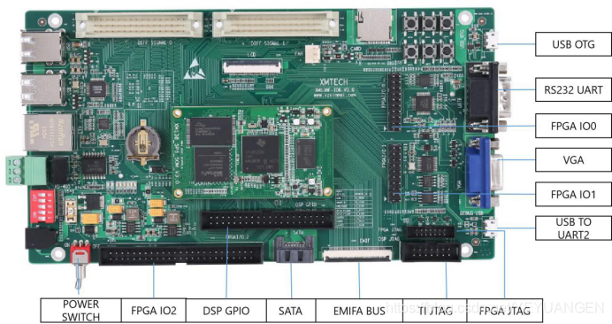
Figure 4 Development board interface diagram