Design and Application of a Software Radio Platform Based on C6748 DSP and FPGA
This article presents a software-defined radio (SDR) platform based on DSP, FPGA, and ASIC technologies. On this experimental platform, the baseband and intermediate frequency (IF) designs of an OFDM system have been implemented and practically verified. The system operates stably and effectively supports multiple communication modes, making it a widely applicable SDR platform. Current research focuses on baseband predistortion techniques for power amplifiers to further enhance system performance.
- Evaluation Board Overview
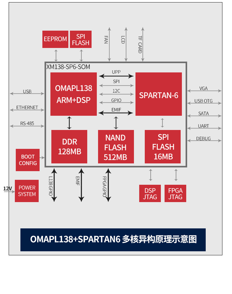
- Features a TI OMAP-L138 processor (fixed/floating-point DSP C674x + ARM9) combined with a Xilinx Spartan-6 FPGA;
- The OMAP-L138 and FPGA are interconnected via uPP, EMIFA, and I2C buses, supporting communication speeds up to 228 MByte/s; the OMAP-L138 runs at a 456 MHz main frequency, delivering up to 3648 MIPS and 2746 MFLOPS computing performance;
- FPGA compatible with Xilinx Spartan-6 models XC6SLX9/16/25/45, enabling strong platform scalability;
- The development board exposes abundant peripherals, including high-speed data interfaces such as Gigabit Ethernet, SATA, EMIFA, uPP, and USB 2.0, as well as common interfaces including GPIO, I2C, RS232, PWM, and McBSP;
- Certified for high- and low-temperature operation, suitable for harsh working environments;
- The DSP + ARM + FPGA tri-core system-on-module (SOM) measures 66 mm × 38.6 mm and uses industrial-grade B2B connectors to ensure signal integrity;
- Supports bare-metal programming, SYS/BIOS, and Linux operating systems.
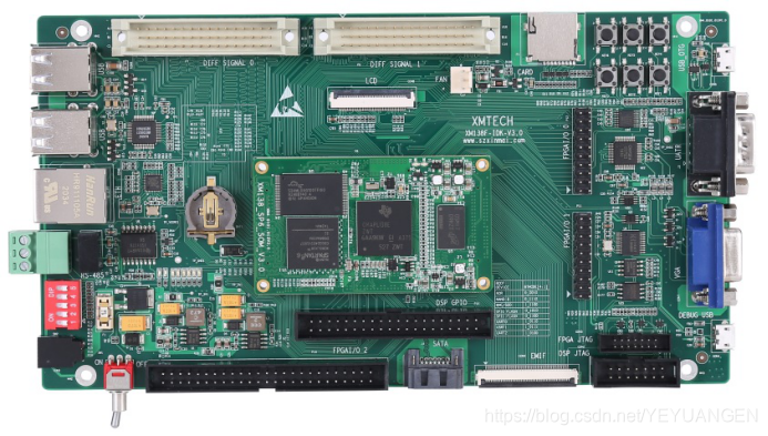
Figure 1: Front and side views of the development board
The XM138F-IDK-V3.0 is a development board designed based on the Shenzhen Xinmen XM138-SP6-SOM core module. It features a 4-layer PCB design with lead-free immersion gold finish, providing users with a test platform for the XM138-SP6-SOM core module to rapidly evaluate its overall performance.
The XM138-SP6-SOM exposes all CPU resource signal pins, making secondary development extremely easy. Customers can focus solely on application-level development, significantly reducing development difficulty and time-to-market, enabling faster product launches and timely market capture. In addition to rich demo programs, comprehensive development tutorials and full technical support are provided to assist customers with carrier board design, debugging, and software development.
- Typical Application Areas
Data acquisition, processing, and display systems
Intelligent power systems
Image processing equipment
High-precision instruments and meters
Mid-to-high-end numerical control systems
Communication equipment
Audio and video data processing
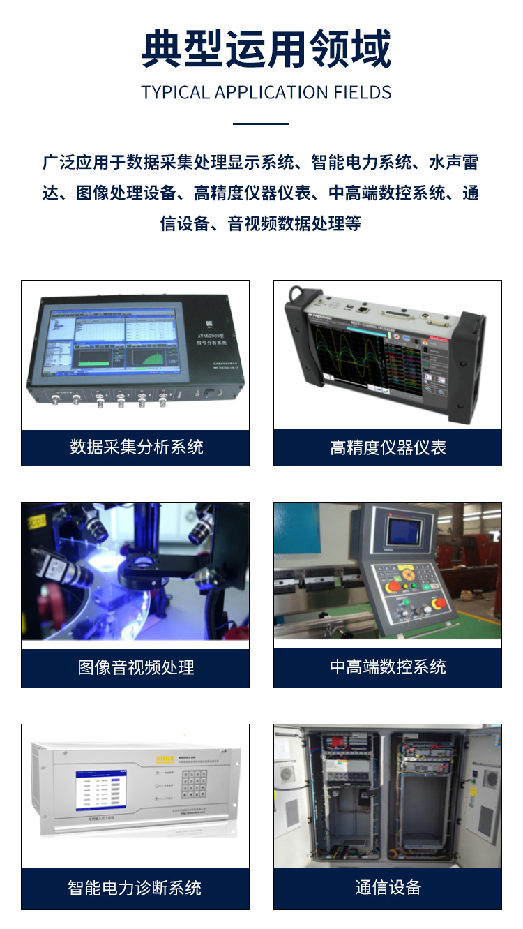
Figure 2: Typical application areas
- Hardware and Software Specifications
Peripheral resource block diagram of the development board
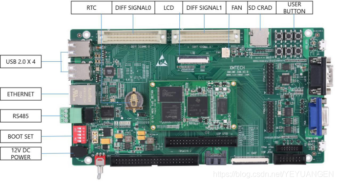
Figure 3: Development board interface diagram
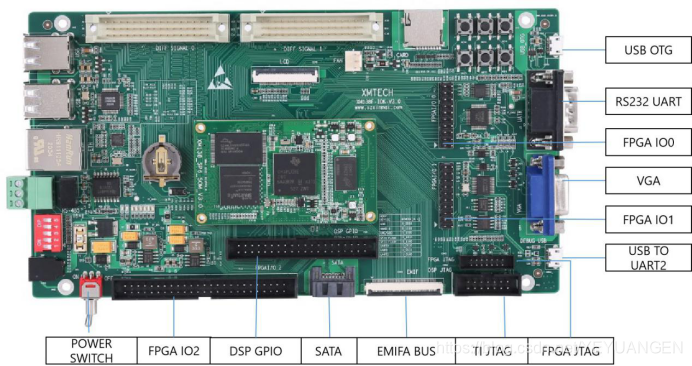
Figure 4: Development board interface diagram