Target Detection Method and Platform Design for C6748 + FPGA Based Angle and Range Measurement Continuous Wave Radar
Frequency Modulated Continuous Wave (FMCW) radar offers advantages such as low cost, large time-bandwidth product, high signal energy, strong anti-clutter capability, and portability. It plays a significant role in specialized measurement, detection, and security applications. Among the various technologies in continuous wave radar, improving measurement accuracy and detection probability is crucial, making in-depth research in these two areas highly significant. The main work of this paper includes: 1. Introducing the specific flowchart and working principle of sawtooth wave FMCW radar, deriving the principles of range, velocity, and angle measurement, and discussing the range-velocity coupling and decoupling problems in sawtooth wave FMCW radar; analyzing range resolution and velocity resolution. 2. Designing an intermediate frequency hardware platform for sawtooth wave FMCW radar based on an FPGA+DSP framework, fully leveraging the parallel logic capabilities of FPGA and the computational power of DSP. The solution mainly includes: an IF signal preprocessing module, a data sampling module, an FPGA signal processing module, DSP module peripheral circuits, UPP communication protocol, and a power module, elaborating on electromagnetic compatibility and layout design considerations for the overall circuit. 3. Deriving, simulating, and validating target detection algorithms for continuous wave radar. This primarily includes: using FIR filters to remove high-frequency background clutter; employing the FFT+Chirp-Z algorithm to improve measurement accuracy against the picket fence effect of the FFT algorithm; proposing improved algorithms to address the masking effect in CA-CFAR detection algorithms and the high false alarm rate of ordered constant false alarm rate algorithms; using an improved MUSIC angle measurement algorithm to overcome the limitation of traditional MUSIC algorithms in measuring coherent signal angles; and proposing a method to feed back data processing results that meet certain requirements into the range, velocity, and angle measurement algorithms for signal processing to improve the efficiency of signal processing algorithms. 4. Separately testing the hardware and software of the entire system, analyzing the test results; then conducting outdoor experiments with the entire radar system, analyzing the test results and the causes of errors, providing a reliable practical basis for further optimization. Experimental results show that the system operates stably, can accurately measure target positions, and the main measured indicators meet the project design requirements, achieving real-time signal processing.
1 Evaluation Board Introduction
- Based on TI OMAP-L138 (fixed-point/floating-point DSP C674x + ARM9) + Xilinx Spartan-6 FPGA processor;
- OMAP-L138 and FPGA are connected via uPP, EMIFA, and I2C bus, with communication speeds up to 228 MByte/s;
- OMAP-L138 main frequency 456MHz, with computing power up to 3648 MIPS and 2746 MFLOPS;
- FPGA compatible with Xilinx Spartan-6 XC6SLX9/16/25/45, strong platform upgrade capability;
- DSP+ARM+FPGA triple-core SOM, size 66mm*38.6mm, using industrial-grade B2B connectors to ensure signal integrity;
- Supports bare metal, SYS/BIOS operating system, and Linux operating system.
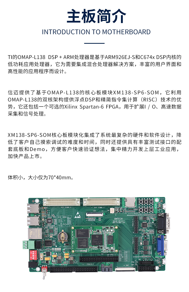 Figure 1 Development board front and side views
The XM138F-IDK-V3.0 is a development board designed based on Shenzhen Xinmai XM138-SP6-SOM core board. It features a 4-layer board design with immersion gold lead-free process, providing users with a test platform for the XM138-SP6-SOM core board to quickly evaluate its overall performance.
The XM138-SP6-SOM exposes all CPU resource signal pins, making secondary development extremely easy. Customers only need to focus on the upper-layer applications, greatly reducing development difficulty and time costs, enabling products to quickly enter the market and seize market opportunities. It provides not only rich demo programs but also detailed development tutorials and comprehensive technical support to assist customers with baseboard design, debugging, and software development.
2 Typical Application Areas Data acquisition, processing, and display systems Intelligent power systems Image processing equipment High-precision instrumentation Mid-to-high-end CNC systems Communication equipment Audio and video data processing
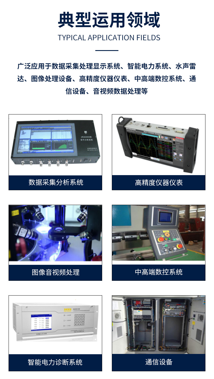 Figure 2 Typical application areas
3 Hardware and Software Parameters
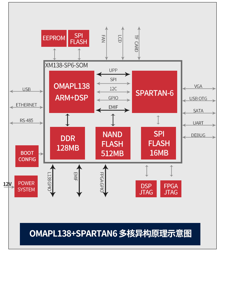 Development board peripheral resource block diagram
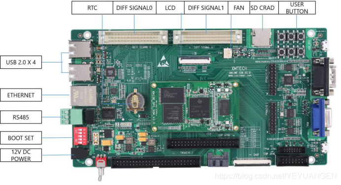
Figure 3 Development board interface diagram
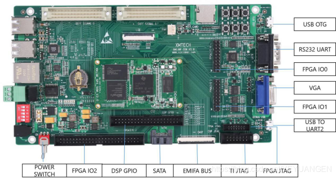
Figure 4 Development board interface diagram
