Modular Design and Implementation of a C6748 DSP+FPGA MIMO Radar Verification System
Unlike traditional radar, MIMO radar has attracted significant research interest in recent years due to its unique advantages. The key benefit of MIMO radar lies in its ability to achieve high angular resolution without being constrained by antenna size. This paper presents the design of a MIMO radar verification system that overcomes the drawbacks of conventional MIMO radar systems, such as large size and long processing time, enabling efficient target localization and imaging. The paper begins with an introduction to the fundamentals of MIMO radar, followed by the design of a modular MIMO radar verification system composed of three main components: a radar signal generator module, a signal processing platform module, and a signal transceiver module. Each module can be independently replaced and tuned according to experimental requirements. Subsequently, the tasks and functions of these three modules within the radar system are described in detail.
Based on the method of MIMO radar signal generation, a DDS-based radar signal generator module controlled by an FPGA is implemented, with detailed discussion on its circuit design and signal selection. Then, through analysis of the overall architecture and functional requirements of the signal processing module for MIMO radar, an intermediate frequency (IF) signal processing module and a DSP+FPGA dual-core control center are designed to handle signal processing tasks, with a detailed explanation of the operational workflow. Following this, the design of the FMCW transceiver and antenna is presented according to the requirements of the MIMO radar system. Specific implementations for each module are provided.
Finally, the functionality of each module in the MIMO radar system is verified individually. The modules are then integrated, and multiple complete imaging experiments are conducted, with results presented and analyzed. Careful observation and analysis confirm that all components of the proposed MIMO radar system are feasible and that the imaging function operates well, making the system suitable for subsequent algorithm validation.
1 Evaluation Board Overview
- Based on TI OMAP-L138 (fixed/floating-point DSP C674x + ARM9) + Xilinx Spartan-6 FPGA processor;
- OMAP-L138 and FPGA connected via uPP, EMIFA, and I2C buses, supporting communication speeds up to 228 MByte/s; OMAP-L138 operates at 456 MHz with computing performance of up to 3648 MIPS and 2746 MFLOPS;
- FPGA compatible with Xilinx Spartan-6 XC6SLX9/16/25/45, offering strong platform scalability;
- The development board exposes abundant peripherals, including Gigabit Ethernet, SATA, EMIFA, uPP, and USB 2.0 for high-speed data transmission, as well as common interfaces such as GPIO, I2C, RS232, PWM, and McBSP;
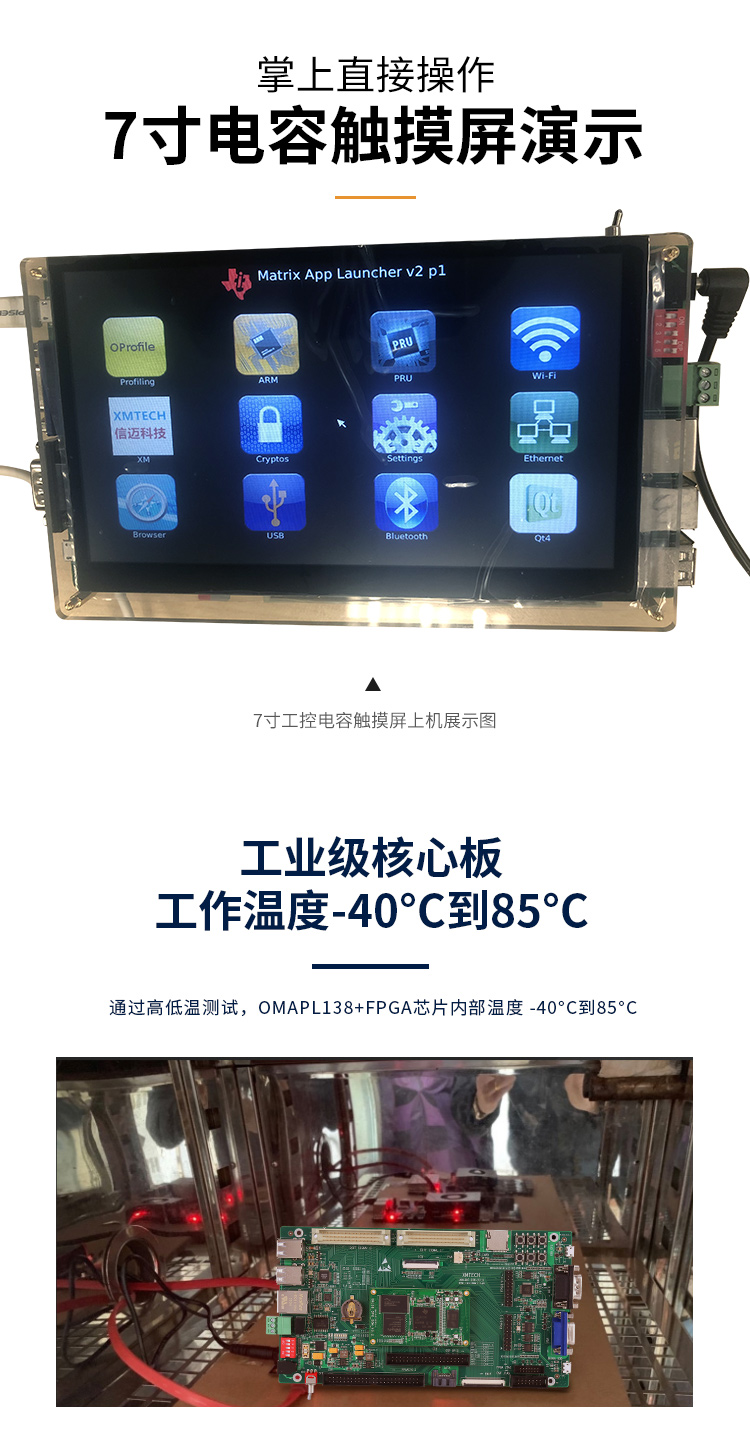
- Passed high and low temperature testing, suitable for operation in harsh environments;
- DSP+ARM+FPGA tri-core SOM (System-on-Module), dimensions 66mm × 38.6mm, using industrial-grade B2B connectors to ensure signal integrity; Ø
- Supports bare-metal, SYS/BIOS, and Linux operating systems.
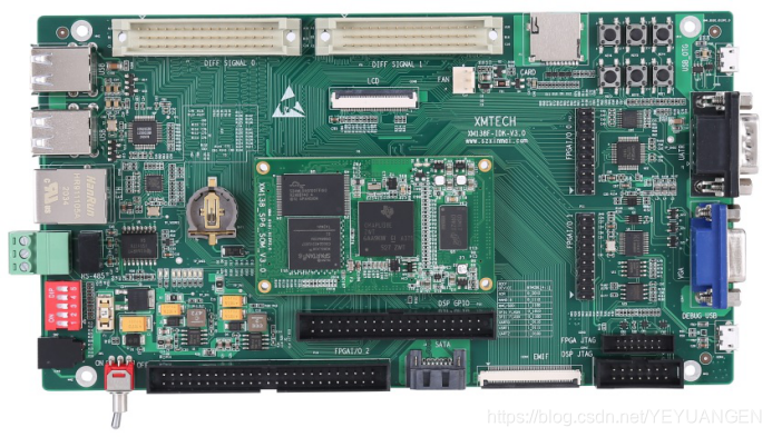
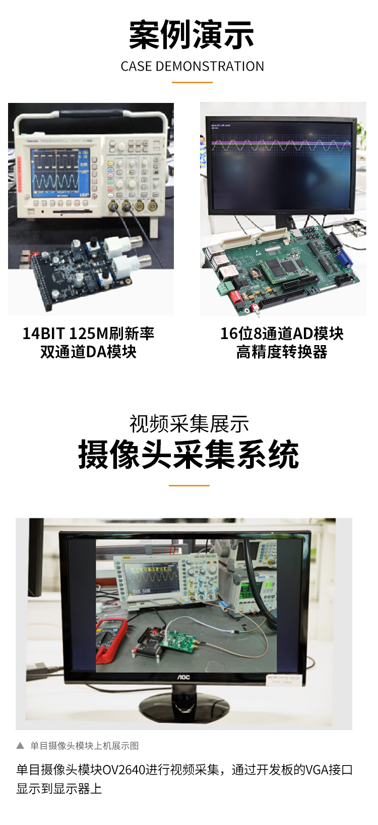
Figure 1 Front and side views of the development board
The XM138F-IDK-V3.0 is a development board designed based on the Shenzhen Xinmai XM138-SP6-SOM core module. It features a 4-layer PCB design with lead-free immersion gold process, providing users with a testing platform for the XM138-SP6-SOM core module to rapidly evaluate its overall performance.
The XM138-SP6-SOM exposes all CPU resource signal pins, making secondary development extremely easy. Customers can focus on application-level development, significantly reducing development difficulty and time cost, accelerating product time-to-market and enabling timely capture of market opportunities. In addition to providing rich demo programs, it also offers detailed development tutorials and comprehensive technical support to assist customers with baseboard design, debugging, and software development.
2 Typical Application Areas
Data acquisition, processing, and display systems
Smart power systems
Image processing equipment
High-precision instruments and meters
Mid-to-high-end CNC systems
Communication equipment
Audio and video data processing
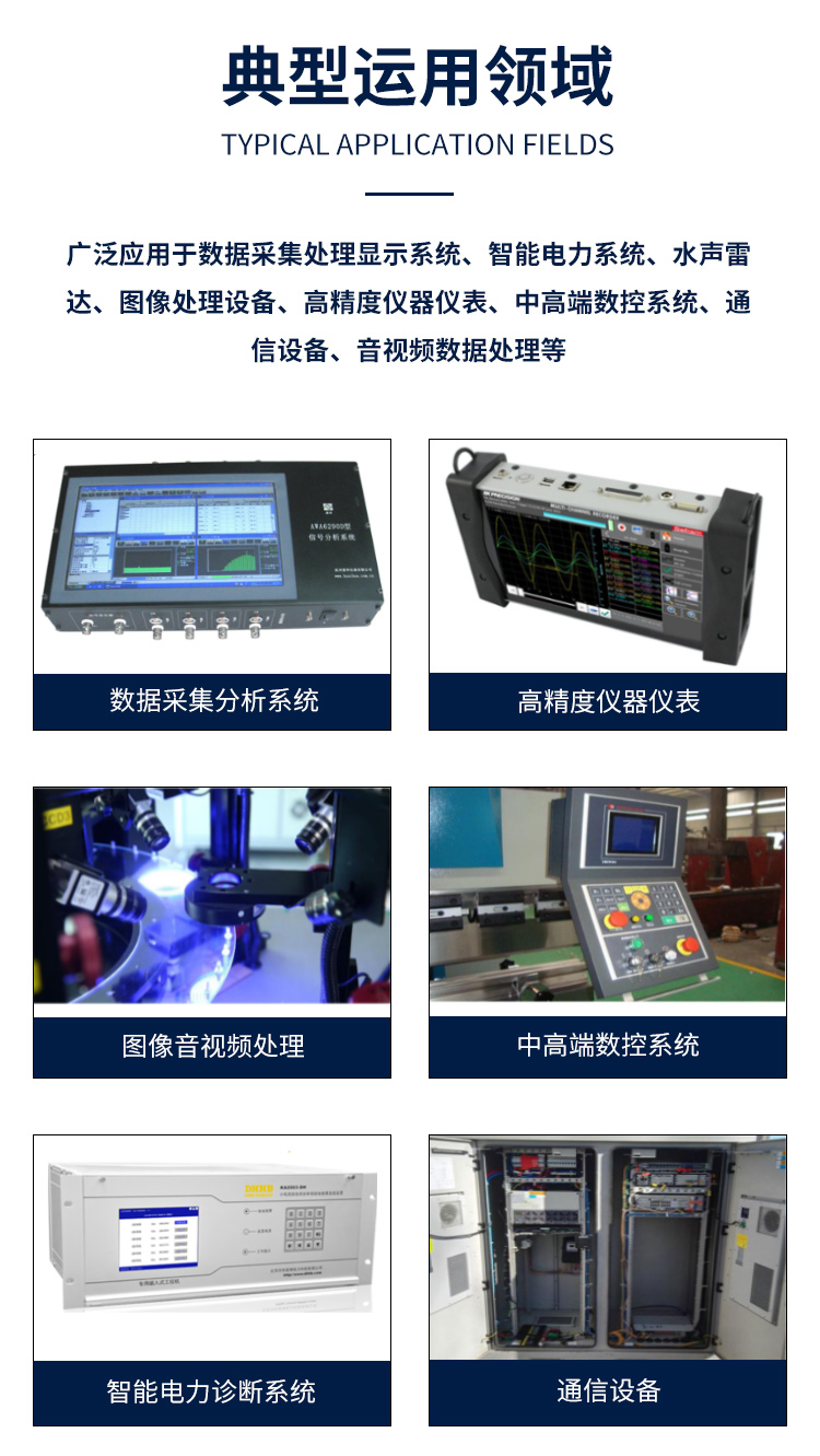
Figure 2 Typical application areas
3 Hardware and Software Specifications
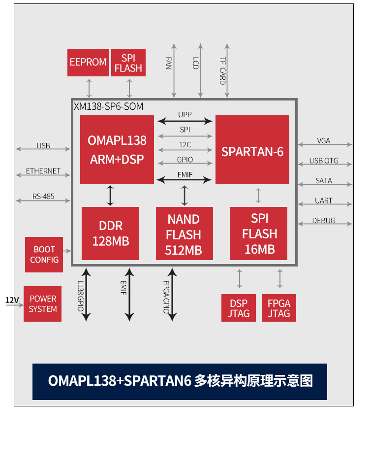
Peripheral resource block diagram of the development board
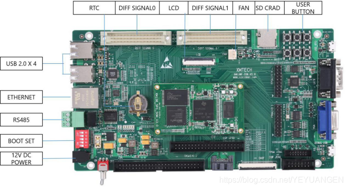
Figure 3 Development board interface diagram
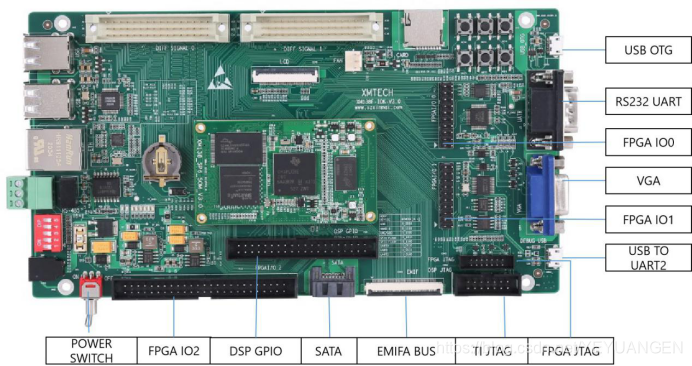
Figure 4 Development board interface diagram