Design of an Embedded Spray Painting Robot Controller Based on OMAPL138 + FPGA
Spray painting is currently one of the most widely used coating methods in many industries. With the development of computer numerical control technology in an increasing number of industries, robotic spray painting has become an increasingly prevalent trend in modern spray painting operations. Foreign robotic spray painting technology is relatively mature, with research dating back to the 1960s. The current spray painting robot market is still dominated by foreign robot brands, such as KUKA from Germany, ABB from Sweden, and FANUC and MOTOMAN from Japan. In contrast, domestic research on spray painting robots started later, and the technology is relatively backward compared to foreign counterparts. Currently, domestic manufacturers do not yet possess the capability to independently produce spray painting robots in a complete sense. Addressing the domestic market demand for the robotic spray painting industry, and based on the current level of domestic spray painting robot development, this project draws upon foreign technology and considers the operational skill level of frontline spray painting workers. This topic proposes a method that uses servo torque control to provide assistance, overcoming the inertial load and joint damping forces during robot teaching. It designs an embedded direct teaching spray painting robot controller based on the OMAPL138 heterogeneous dual-core processor + FPGA. This paper combines the functional hierarchy of the embedded direct teaching spray painting robot controller, focusing on the application of FPGA in the controller, and researches the overall scheme of the controller, software platform construction, hardware circuit design, and FPGA-based device layer control software design and implementation. Based on the functional requirements and design goals of the robot controller, the controller is divided into three layers: interface layer, control layer, and device layer. The ARM core of the OMAPL138 in the controller is responsible for communication with the robot operation interface and system management; the DSP core is responsible for robot coordinate transformation, joint interpolation, sampled information processing, and assistance algorithms; the FPGA is responsible for controlling and detecting robot devices. The paper also analyzes the overall design scheme of the OMAPL138+FPGA-based spray painting robot controller, as well as the design of its hardware and software platforms. Combining the hardware structure layout and power planning and design of the OMAPL138+FPGA-based spray painting robot controller, it introduces the hardware resources of the OMAPL138 core board, with a focus on elaborating the circuit design of the FPGA expansion backplane and terminal board. For the communication interface scheme between OMAPL138 and FPGA, it analyzes the hardware circuit based on EMIFA bus communication and designs an FPGA-based FIFO for EMIFA communication with OMAPL138. For servo signal sampling, position/torque control and switching, and I/O device signal detection and control, the paper researches the software design and implementation of the FPGA-based spray painting robot controller, including incremental pulse sampling modules, DAC controllers, digital/pulse conversion modules, and I/O monitoring modules, providing underlying support for spray painting robot teaching, assistance, and reproduction. Finally, functional tests of the spray painting robot controller are conducted, and workpiece trial spray painting is performed using the robot to verify whether the controller can achieve robot spray painting teaching and reproduction functions, and whether it can achieve the expected spray painting effect. Currently, the controller, after functional testing and verification, has been applied in the spray painting robot system of a company in Foshan. It is the most widely used coating method, with more and more industries focusing on coating quality, efficiency, and complexity.
1 Evaluation Board Introduction Based on TI OMAP-L138 (fixed-point/floating-point DSP C674x + ARM9) + Xilinx Spartan-6 FPGA processor; OMAP-L138 FPGA connects via uPP, EMIFA, I2C bus, with communication speeds up to 228MByte/s; OMAP-L138 main frequency 456MHz, with computing power up to 3648MIPS and 2746MFLOPS; FPGA compatible with Xilinx Spartan-6 XC6SLX9/16/25/45, strong platform upgrade capability; The development board exposes rich peripherals, including Gigabit Ethernet, SATA, EMIFA, uPP, USB 2.0 and other high-speed data transfer interfaces, as well as common interfaces such as GPIO, I2C, RS232, PWM, McBSP; Certified through high and low-temperature tests, suitable for various harsh working environments; DSP+ARM+FPGA triple-core module, size 66mm*38.6mm, uses industrial-grade B2B connectors to ensure signal integrity; Supports bare-metal, SYS/BIOS operating system, Linux operating system.
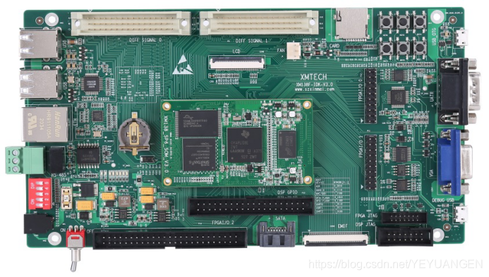 Figure 1 Front and Side View of the Development Board
The XM138F-IDK-V3.0 is a development board designed based on Shenzhen Xinmai's XM138-SP6-SOM core board. It adopts a 4-layer board design with immersion gold lead-free process, providing users with a test platform for the XM138-SP6-SOM core board to quickly evaluate its overall performance.
The XM138-SP6-SOM exposes all CPU resource signal pins, making secondary development extremely easy. Customers only need to focus on the upper-layer applications, greatly reducing development difficulty and time costs, allowing products to quickly enter the market and seize market opportunities. It provides not only rich demo programs but also detailed development tutorials and comprehensive technical support to assist customers with baseboard design, debugging, and software development.
2 Typical Application Areas Data acquisition, processing, and display systems Smart power systems Image processing equipment High-precision instrumentation Mid-to-high-end CNC systems Communication equipment Audio and video data processing
Figure 2 Typical Application Areas
3 Software and Hardware Parameters Development Board Peripheral Resource Block Diagram
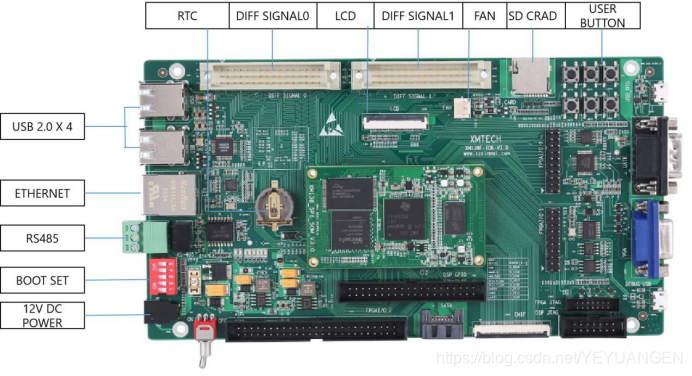
Figure 3 Development Board Interface Diagram
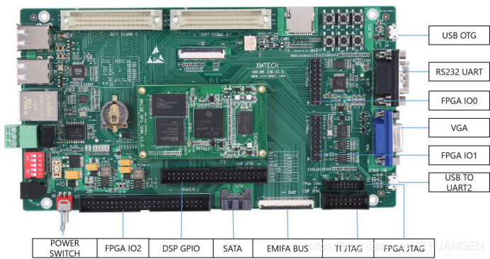
Figure 4 Development Board Interface Diagram