AM5728 DSP JTAG Connection and Debugging Method
1 Applicability Description
This example primarily demonstrates connecting to the DSP core using an emulator via the JTAG interface. The example is based on the Ximai XM138-IDK-V3 AM5728 development board.
2 Emulator Connection to DSP in Debug Mode
- Experiment Steps****:****
- Install CCS6.1.3 according to the instructions in the software installation manual. Pay attention to updating the relevant emulator drivers as per the document.
- Select Debug boot mode for the development board, set the DIP switches to 11111, and connect the emulator to the JTAG interface.
If using an XDS200 or XDS560V2 emulator, ensure to update the emulator firmware and drivers.
- Open CCS, configure the file, connect the ARM core, then connect the DSP core.
In the CCS interface, click View, then click Target Configurations.
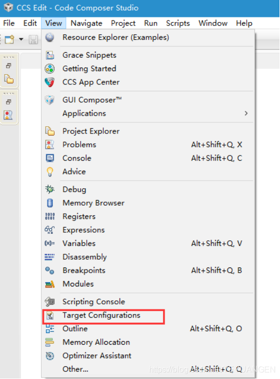
Figure 1
Right-click in the pop-up target configuration window and create a new configuration.
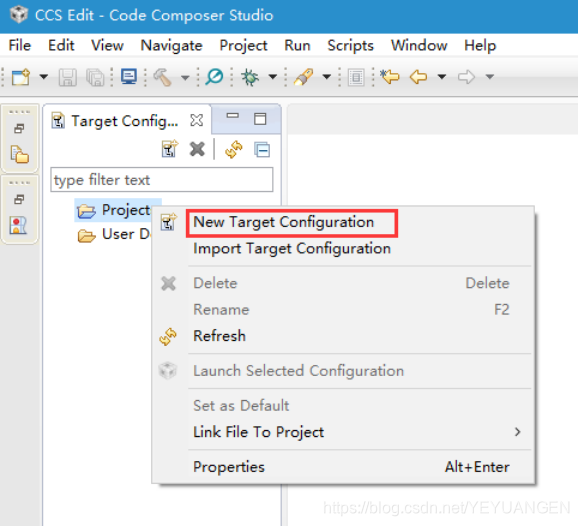
Figure 2
Modify the target configuration file name for easy identification, such as AM5728.ccxml or AM57xx.ccxml.
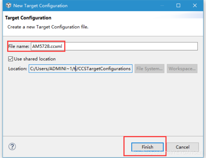
Figure 3
Click Finish to enter the target configuration. Select the corresponding emulator model. This experiment uses an XDS100V3 emulator.
If using an XDS200 emulator, select the option; for the chip model, select GPEVM_AM572x. This configuration will automatically load TI's official GEL file.
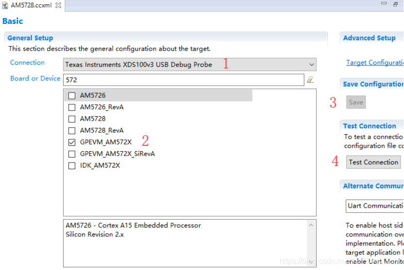
Figure 4
After clicking save, click Test Connection. If the result is as shown in the figure below, the connection test is successful.
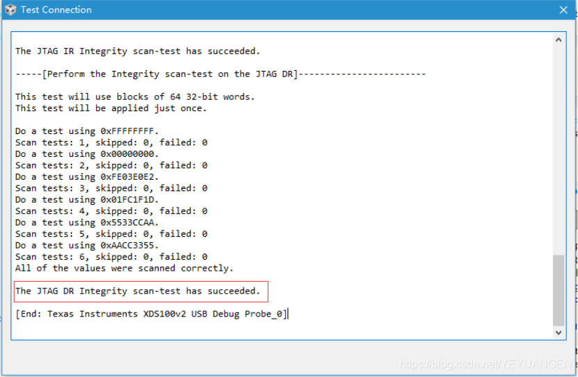
Figure 5
In the emulator configuration window, select the completed target configuration, right-click, and click Launch Selected Configuration.
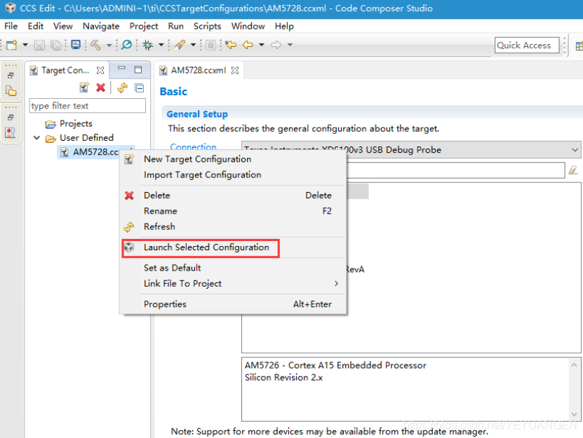
Figure 6
Enter the Debug interface. In the Debug window, right-click on the CortexA15_0 core and click Connect Target, as shown below.
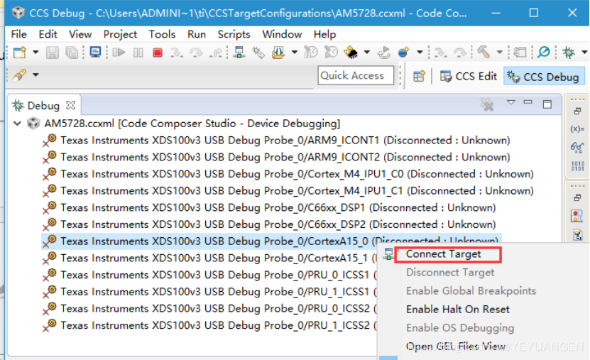
Figure 7
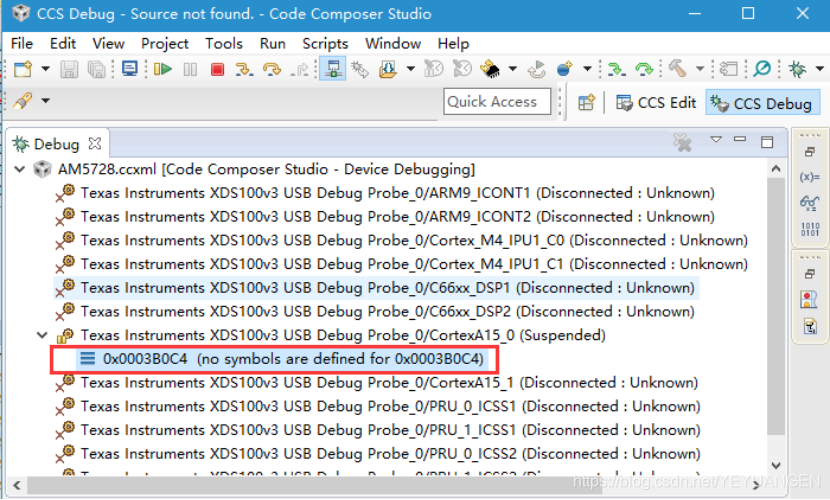
Figure 8
Right-click on the C66xx_DSP1 core and click Connect Target, as shown below. To successfully connect to the DSP core, you must first connect to the ARM core to initialize and enable the DSP core, and then connect to the DSP core.
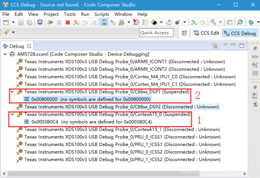
Figure 9
3 Emulator Connection to DSP under Linux System
- Experiment Steps
- Install CCS6.1.3 according to the instructions in the software installation manual. Pay attention to updating the relevant emulator drivers as per the document.
- Select SD card boot mode for the development board, set the DIP switches to 01000, and connect the emulator to the JTAG interface.
If using an XDS200 or XDS560V2 emulator, ensure to update the emulator firmware and drivers.
- Open CCS, configure the file.
- Open the serial port window.
- Connect to DSP1 in CCS.
In the CCS interface, click View, then click Target Configurations.
Figure 10
Right-click in the pop-up target configuration window and create a new configuration.
Figure 11
Modify the target configuration file name for easy identification, such as AM5728.ccxml or AM57xx.ccxml.
Figure 12
Click Finish to enter the target configuration. Select the corresponding emulator model. This experiment uses an XDS100V3 emulator.
If using an XDS200 emulator, select the option; for the chip model, select AM5728.
Figure 13
After clicking save, click Test Connection. If the result is as shown in the figure below, the connection test is successful.
Figure 14
In the emulator configuration window, select the completed target configuration, right-click, and click Launch Selected Configuration.
Figure 15
After clicking Launch Selected Configuration, the following interface appears.
Figure 16
Open the serial port window and enter the following command:
Target# echo "on" > /sys/ bus /platform/devices/40800000.dsp/power/control
Figure 17
Return to the CCS Debug interface. In the Debug window, right-click on the C66xx_DSP1 core and click Connect Target, as shown below.
Figure 18
After the DSP core is connected, it will appear as shown in the figure below. Copy the GPIO_LedBlink_evmAM572x_c66xTestProject.out file located at “\Demo\RTOS\c66\led\bin\” to a path that does not contain Chinese characters, then click the load button in the red box to upload the compiled GPIO_LedBlink_evmAM572x_c66xTestProject.out file. After selecting the path, click OK to upload.
Figure 19
Figure 20
After the upload is complete, as shown in the figure below, the program can be debugged using CCS.
Figure 21