AM335X and AM5728 NOR Flash Boot
Below is a summary of key design considerations for implementing NOR flash boot on the AM335X, provided for your reference.
- NOR Flash Boot Overview
Refer to section 26.1.7.2 "XIP Memory" in the Technical Reference Manual (TRM) for detailed information. This section will not be elaborated further here.
- Design Considerations
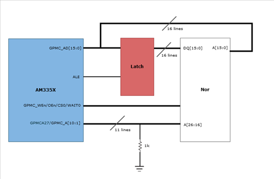
Due to the limited number of pins on the AM335X, many customers consider using multiplexed GPMC data and address lines when interfacing with external NOR flash. This allows the GPMC_AD[15:0] lines to serve dual purposes: as 16-bit data lines and as the lower 16 bits of the address bus.
In such configurations, what specific design aspects should be considered?
In this setup, GPMC_AD functions as both the 16-bit data bus and the lower 16-bit address bus. According to Table 7-5 "GPMC Pin Multiplexing Options" in the TRM, GPMC_A[10:1] are used as higher-order address lines for the NOR flash. These GPMC_A[10:1] signals support two multiplexing options: they can be assigned to one pin group in pinmux mode 0, or to another group in pinmux mode 1.
Signal
ZCZ Pin Map (Pinmux mode 0)
ZCZ Pin Map (Pinmux mode 1)
GPMC_A1
V14
R2
GPMC_A2
U14
R3
GPMC_A3
T14
R4
GPMC_A4
R14
T1
GPMC_A5
V15
T2
GPMC_A6
U15
T3
GPMC_A7
T15
T4
GPMC_A8
V16
U5
GPMC_A9
U16
R5
GPMC_A10
T16
V5
When designing the schematic for these two connection options, please note the following:
(1) When using the pinmux mode 0 pin group:
(a) The latch must be edge-triggered (rising edge), not level-sensitive. This is because the AM335x ROM code uses a fixed GPMC timing sequence during NOR flash boot.
(b) The higher-order address lines must be pulled down. The ROM code initializes only GPMC_AD[15:0] during NOR flash boot and does not initialize GPMC_A[10:1]. To ensure the ROM code correctly recognizes the NOR flash address space early in boot, the high-order address lines must be actively pulled low.
(2) When using the pinmux mode 1 connection:
In this case, GPMC_A[10:1] are multiplexed with LCD_DATA signals, which are used as SYSBOOT pins during early boot and have internal pull-up or pull-down resistors based on the selected boot mode. This conflicts with requirement (1), which requires GPMC_A[10:1] to remain pulled low during initial NOR flash boot. Therefore, a bus transceiver must be added to isolate these two functions. See the figure below.
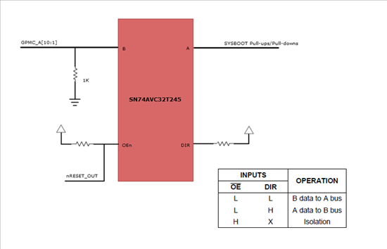
The state of the SYSBOOT pins is only sampled at the rising edge of PORz. The warm reset input pin nRESET_OUT remains low for a period after PORz completes. Refer to Figure 8-19 "PORz" in the TRM. This signal can be used as the control signal for the bus transceiver. When nRESET_OUT is low, according to the logic of the SN74AVC32T245, the bus connection is from side A to side B, allowing the SYSBOOT pin states to be read during the rising edge of PORz. After nRESET_OUT remains low for a certain duration and then transitions high, the bus transceiver isolates GPMC_A[10:1] (side A) from the SYSBOOT pull-up/pull-down resistors (side B).
Software Considerations:
Starting from SDK version 05.06.00.00, U-Boot includes support for NOR flash boot. When using this feature, note the following:
NOR flash is an XIP (eXecute-In-Place) memory, meaning the SPL does not need to be copied into RAM to execute—it can run directly from NOR flash. However, during NOR flash boot, the ROM code only initializes the lower 16 bits of the address bus, so only a 64KB × 16-bit address space starting at 0x08000000 is accessible at boot time. During initialization, u-boot.bin will configure the higher-order address lines so that the AM335X can subsequently access the full NOR flash address space.
The high-order address line initialization code is located in the s_init function in u-boot/board/ti/am335x/board.c:
#ifdef CONFIG_NOR_BOOT
asm("stmfd sp!, {r2 - r4}");
asm("movw r4, #0x8A4");
asm("movw r3, #0x44E1");
asm("orr r4, r4, r3, lsl #16");
asm("mov r2, #9");
asm("mov r3, #8");
asm("gpmc_mux: str r2, [r4], #4");
asm("subs r3, r3, #1");
asm("bne gpmc_mux");
asm("ldmfd sp!, {r2 - r4}");
#endif
When using pinmux mode 1 from the table above—i.e., when the NOR flash high-order address lines GPMC_A[10:1] are connected to the pinmux mode 1 pin group—no changes to U-Boot are required. However, if the pinmux mode 0 pin group is used, modify the code as follows:
#ifdef CONFIG_NOR_BOOT
asm("stmfd sp!, {r2 - r4}");
asm("movw r4, #0x844"); /* Start point changed from LCD_DATA1 to GPMC_A1 /
asm("movw r3, #0x44E1");
asm("orr r4, r4, r3, lsl #16");
asm("mov r2, #8"); / Changed from #9 to #8, GPMC_A1 to GPMC_A11 in mode 0 /
asm("mov r3, #11"); / Changed from #8 to #11, as there are 11 lines */
asm("gpmc_mux: str r2, [r4], #4");
asm("subs r3, r3, #1");
asm("bne gpmc_mux");
asm("ldmfd sp!, {r2 - r4}");
#endif
Additionally, SYSBOOT settings differ depending on the connection used. If using the pinmux mode 0 pin group, configure SYSBOOT to select XIP (mux1) or XIP (mux1) w/WAIT0 boot mode. If using pinmux mode 1, configure SYSBOOT for XIP (mux2) or XIP (mux2) w/WAIT0 boot mode.
For AM5728 technical discussions, please add WeChat: 13670212541